Table of Contents
Advertisement
Quick Links
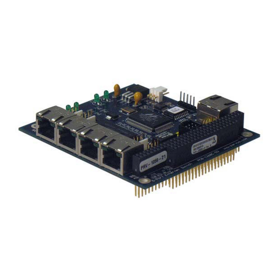
Parvus PRV-1059-21
5-Port PC/104 10/100 Fast Ethernet Switch
A l l t r a d e m a r k s , b r a n d n a m e s , a n d b r a n d s a p p e a r i n g h e r e i n a r e t h e p r o p e r t y o f t h e i r r e s p e c t i v e o w n e r s .
• C r i t i c a l a n d e x p e d i t e d s e r v i c e s
• I n s t o c k / R e a d y - t o - s h i p
Artisan Scientific Corporation dba Artisan Technology Group is not an affiliate, representative, or authorized distributor for any manufacturer listed herein.
In Stock
Used and in Excellent Condition
Open Web Page
https://www.artisantg.com/94160-1
• We b u y y o u r e x c e s s , u n d e r u t i l i z e d , a n d i d l e e q u i p me n t
• F u l l - s e r v i c e , i n d e p e n d e n t r e p a i r c e n t e r
Advertisement
Table of Contents

Related Manuals for Parvus PRV-1059-21


Summary of Contents for Parvus PRV-1059-21
- Page 1 Parvus PRV-1059-21 5-Port PC/104 10/100 Fast Ethernet Switch In Stock Used and in Excellent Condition Open Web Page https://www.artisantg.com/94160-1 A l l t r a d e m a r k s , b r a n d n a m e s , a n d b r a n d s a p p e a r i n g h e r e i n a r e t h e p r o p e r t y o f t h e i r r e s p e c t i v e o w n e r s .
- Page 2 USER MANUAL PRV-1059 5-Port PC/104 10/100 Fast Ethernet Switch MNL-0490-01 Rev D4 REF. ECO-3163 01 Feb 10 RUGGED SOLUTIONS FOR REAL WORLD APPLICATIONS www.parvus.com Artisan Technology Group - Quality Instrumentation ... Guaranteed | (888) 88-SOURCE | www.artisantg.com...
- Page 3 Parvus reserves the right to change the contents and form of this document, as well as the features and specifications of its products at any time without notice.
-
Page 4: Table Of Contents
PRV-1059 User Manual Table of Contents Table of Contents ..............................3 Chapter 1 Introduction ............................5 Functional Description ............................5 Features ................................6 About PC/104............................... 6 Chapter 2 Quick Start-up ..........................7 Installation ................................7 Installing Network Cables and Establishing Connectivity ................7 Chapter 3 Connector Description ........................ - Page 5 PRV-1059 User Manual Technical Specification ............................21 Electrical ..............................21 Environmental Specifications..........................21 Temperature..............................21 Reliability (MTBF)............................... 21 Mechanical ................................. 21 Weight ................................. 21 Dimensions..............................22 Chapter 6 Troubleshooting..........................24 Technical Assistance ............................24 Returning For Service ............................24 Chapter 7 Contact Info ............................
-
Page 6: Chapter 1 Introduction
The 4-pin Molex headers enable embedded systems to optionally mount RJ-45 jacks in a faceplate, endcap or enclosure using a Parvus cable set (sold separately), which includes five female Molex to RJ-45 adapters. Power connections can be made through either the PC/104 (ISA) bus or externally through a 2-pin Molex connector. -
Page 7: Features
PRV-1059 User Manual Features RJ-45 jack or Molex Ethernet connectors LED activity indicators Link/activity and speed LED’s available on separate connectors Low power dissipation Store-and-forward switching mode 5 Auto-configured ports (straight/twist cable connections) Auto-negotiation and speed auto-sensing support ... -
Page 8: Chapter 2 Quick Start-Up
2-pin power header, depending on the version purchased. The VLAN-enabled switch requires use of the Parvus cable (sold separately) and software to configure the VLAN settings. Configuration and connection of the VLAN switch is described in chapter 5. -
Page 9: Chapter 3 Connector Description
PRV-1059 User Manual Chapter 3 Connector Description This chapter provides a brief description of the connectors located on the 10/100 Ethernet Switch. Molex Connectors Connector Part Numbers Ethernet (4-pin right angle) P/N: 22-12-2044; mating P/N: 10-11-2043 Power (2-pin right angle) P/N: 22-12-2024;... -
Page 10: 10/100 Ethernet Switch (W/ 4-Pin Molex Ethernet Connectors)
PRV-1059 User Manual 10/100 Ethernet Switch (w/ 4-pin Molex Ethernet Connectors) MNL-0490-01 RevD4 REF. ECO-3163 Effective: 01 Feb 10 Page 9 of 27 Artisan Technology Group - Quality Instrumentation ... Guaranteed | (888) 88-SOURCE | www.artisantg.com... -
Page 11: Connector Pinouts
PRV-1059 User Manual Connector Pinouts Molex Ethernet Pin Description: Ports 0-4 Molex Connector P/N: 22-12-2044; mating P/N: 10-11-2043 Signal RX + RX - TX + CON2/J101: 2-Pin Power Connector (Not Loaded on PC/104 Versions) Molex Connector P/N: 22-12-2024; mating P/N: 10-11-2023 Signal Pin 1 +5VDC (closest to mounting hole) -
Page 12: J1/J3: Pc/104 Bus
PRV-1059 User Manual J1/J3: PC/104 Bus Row A Row B Row C Row D /Iock /SBHE /MCS16 Rstdrv LA23 /IOCS16 LA22 IRQ10 IRQ9 LA21 IRQ11 LA20 IRQ12 DRQ2 LA19 IRQ15 -12v LA18 IRQ14 /Exfer LA17 /DA0 +12v DRQ0 Iordy (key) /DA5 /SMW DRQ5... -
Page 13: Chapter 4 Operational Description
PRV-1059 User Manual Chapter 4 Operational Description This chapter explains the operation of the switch. Switch Data Flow The switching portion of the PRV-1059 receives good packets from the MAC’s, processes them, and forwards them to the appropriate MACs for transmission. Processing the frames is the key activity, and involves the Ingress Policy, the Queue Controller, the Output Queues, and the Egress Policy blocks shown below. -
Page 14: Half- And Full-Duplex Flow Control
PRV-1059 User Manual Half- and Full-Duplex Flow Control Half- and Full-duplex flow control is used to throttle the end station to avoid dropping packets during network congestion. When the free buffer space is almost empty or the output queue is almost full, the MACs force a collision in the input port when sensing an incoming packet. -
Page 15: Address Aging
The following diagrams are similar to those which can be seen within the Parvus VLAN software and are included to illustrate the concept of VLAN on the PRV-1059. Figure 1 below shows a switch and all five ports with no restrictions;... - Page 16 PRV-1059 User Manual Figure 1) Non-VLAN configured state. Unlike Figure 1 above, a VLAN configured switch limits which ports can communicate with each other. The following diagram is a sample of the way that the switch may be setup. Figure 2) Known VLAN configuration Figure 2 is VLAN configuration where Ports 0, 1, and 2 form a VLAN.
-
Page 17: Vlan Software Quick Start Setup Guide
PRV-1059 User Manual VLAN Software Quick Start Setup Guide In order to change the VLAN configuration on the PRV-1059 5-port Switch, Parvus has provided the user with a simple-to-use GUI program. Implementation of the program is through an RS-232 serial cable connection between a COM port on the host computer and the serial port on the switch. -
Page 18: Software Guide
PRV-1059 User Manual Software Guide This section describes how to use the VLAN GUI program to set up VLAN configurations on the PRV-1059. A screen shot of the program is shown below. Figure 4) VLAN GUI Window Com Port In order to program the PRV-1059, the computer running the software must be connected to the serial port of the switch. -
Page 19: Setting The Egress Ports
PRV-1059 User Manual Setting the Egress Ports Since port-based VLANs only govern outgoing traffic, it necessary to define the egress for all ports. An egress port is defined as the port to which data packets are sent. A visual example is provided below. Figure 5) Egress Port Port-based VLAN egress ports for Figure 5: Egress port for Port 0 : Port 4... -
Page 20: Operation Of Vlan Gui Window
VLAN operation button area for “Apply”, “Reset”, “Query”, “Update”, “Clear all”, “SET”, “GET” and “Exit”. d) Parvus logo area. The operation button area is the most important area because all VLAN configurations, setting displays, executing the VLAN commands will be implemented by these buttons. -
Page 21: Menu Operation
VLAN configuration schemes. Note this does not affect the current VLAN settings of the switch. SET– This button is used for internal troubleshooting or testing by Parvus. Typing a command in the text box on the top right of the GUI window, and then pressing this button will set the switch’s registers. -
Page 22: Chapter 5 Specifications
PRV-1059 User Manual Chapter 5 Specifications This chapter provides the specifications for the PRV-1059. Technical Specification Electrical Requirements +5VDC Input Power Consumption Max: +5 VDC @ 0.44A or 2.2 Watts (0.45W base + 0.35W per port used) Environmental Specifications This section describes the environmental standards that the PRV-1059 has either been designed to meet or tested to. -
Page 23: Dimensions
PRV-1059 User Manual Dimensions 3.550” x 3.775” RJ-45 Version Warning: PC/104 specifications state that max height may only be 0.435”. Be sure that the board height of 0.52” for the RJ-45 version will operate in your application. This applies to the RJ-45 version only. Page 22 of 27 MNL-0490-01 RevD4 REF. - Page 24 PRV-1059 User Manual Molex Version Molex Version Note: The external power connector (J101) on models without the PC/104 bus is a right angle two-pin Molex connector that extends from the board .32” Note: For further information about the mechanical dimensions of ISA and PCI buses please refer to the PC/104 Consortium site (www.pc104.org) MNL-0490-01 RevD4 REF.
-
Page 25: Chapter 6 Troubleshooting
Phone: +1 (801) 433-4322 Fax: +1 (801) 483-1523 Returning For Service Before returning any Parvus product, please fill out a Returned Material Authorization (RMA) request form available for download from the following website under the support section: www.parvus.com Email this form to the email address listed above to receive authorization for shipment. -
Page 26: Chapter 7 Contact Info
PRV-1059 User Manual Chapter 7 Contact Info Main Phone: +1 (801) 483-1533 Fax: +1 (801) 483-1523 Sales +1(800) 483-3152 or (801) 483-1533, sales@parvus.com Product Technical Support +1 (801) 433-6322, tsupport@parvus.com Customer Feedback feedback@parvus.com Company contact info: ® Parvus Corporation 3222 S. Washington St. -
Page 27: Eurotech Group Worldwide Presence
China PARVUS EUROTECH VANTRON Tel. +1 800.483.3152 Tel. +44 (0) 1223.403410 Tel. +86 28.85.12.39.30 +1 801.483.1523 +44 (0) 1223.410457 +86 28.85.12.39.35 E-mail: sales@parvus.com E-mail: sales.uk@eurotech.com E-mail: sales@vantrontech.com.cn E-mail: tsupport@parvus.com E-mail: support.uk@eurotech.com E-mail: support.cn@eurotech.com Web: www.parvus.com Web: www.eurotech.com Web: www.vantrontech.com.cn France EUROTECH Tel. - Page 28 Artisan Technology Group - Quality Instrumentation ... Guaranteed | (888) 88-SOURCE | www.artisantg.com...
Need help?
Do you have a question about the PRV-1059-21 and is the answer not in the manual?
Questions and answers