
Related Manuals for Parvus PRV-1059


Summary of Contents for Parvus PRV-1059
- Page 1 USER MANUAL PRV-1059 5-Port PC/104 10/100 Fast Ethernet Switch MNL-0490-01 Rev D4 REF. ECO-3163 01 Feb 10 RUGGED SOLUTIONS FOR REAL WORLD APPLICATIONS www.parvus.com...
- Page 2 Parvus reserves the right to change the contents and form of this document, as well as the features and specifications of its products at any time without notice.
-
Page 3: Table Of Contents
PRV-1059 User Manual Table of Contents Table of Contents ..............................3 Chapter 1 Introduction ............................5 Functional Description ............................5 Features ................................6 About PC/104............................... 6 Chapter 2 Quick Start-up ..........................7 Installation ................................7 Installing Network Cables and Establishing Connectivity ................7 Chapter 3 Connector Description ........................ - Page 4 PRV-1059 User Manual Technical Specification ............................21 Electrical ..............................21 Environmental Specifications..........................21 Temperature..............................21 Reliability (MTBF)............................... 21 Mechanical ................................. 21 Weight ................................. 21 Dimensions..............................22 Chapter 6 Troubleshooting..........................24 Technical Assistance ............................24 Returning For Service ............................24 Chapter 7 Contact Info ............................
-
Page 5: Chapter 1 Introduction
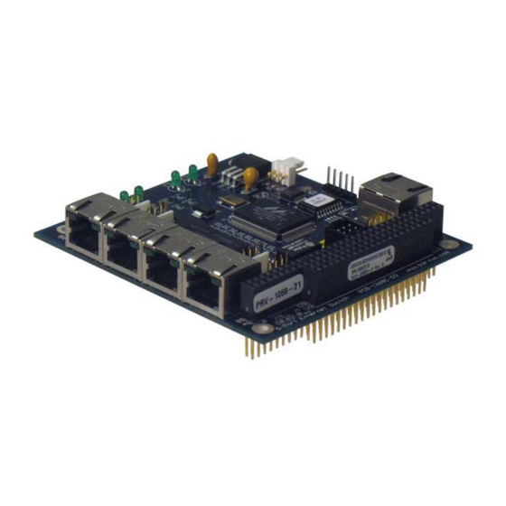
This section provides a functional description of the PRV-1059. Functional Description PRV-1059 is a rugged VLAN-capable 5-port PC/104 Fast Ethernet switch featuring very low power consumption and highly reliable extended-temperature operation up to +85°C (185°F). Supporting auto-MDI-MDIX network installation, the board is designed for simple plug-and-play operation, enabling up to five embedded computing devices to be networked together using 10BaseT or 100BaseTX Local Area Network (LAN) connections. -
Page 6: Features
PRV-1059 User Manual Features RJ-45 jack or Molex Ethernet connectors LED activity indicators Link/activity and speed LED’s available on separate connectors Low power dissipation Store-and-forward switching mode 5 Auto-configured ports (straight/twist cable connections) ... -
Page 7: Chapter 2 Quick Start-Up
2-pin power header, depending on the version purchased. The VLAN-enabled switch requires use of the Parvus cable (sold separately) and software to configure the VLAN settings. Configuration and connection of the VLAN switch is described in chapter 5. -
Page 8: Chapter 3 Connector Description
PRV-1059 User Manual Chapter 3 Connector Description This chapter provides a brief description of the connectors located on the 10/100 Ethernet Switch. Molex Connectors Connector Part Numbers Ethernet (4-pin right angle) P/N: 22-12-2044; mating P/N: 10-11-2043 Power (2-pin right angle) P/N: 22-12-2024;... -
Page 9: 10/100 Ethernet Switch (W/ 4-Pin Molex Ethernet Connectors)
PRV-1059 User Manual 10/100 Ethernet Switch (w/ 4-pin Molex Ethernet Connectors) MNL-0490-01 RevD4 REF. ECO-3163 Effective: 01 Feb 10 Page 9 of 27... -
Page 10: Connector Pinouts
PRV-1059 User Manual Connector Pinouts Molex Ethernet Pin Description: Ports 0-4 Molex Connector P/N: 22-12-2044; mating P/N: 10-11-2043 Signal RX + RX - TX + CON2/J101: 2-Pin Power Connector (Not Loaded on PC/104 Versions) Molex Connector P/N: 22-12-2024; mating P/N: 10-11-2023... -
Page 11: J1/J3: Pc/104 Bus
PRV-1059 User Manual J1/J3: PC/104 Bus Row A Row B Row C Row D /Iock /SBHE /MCS16 Rstdrv LA23 /IOCS16 LA22 IRQ10 IRQ9 LA21 IRQ11 LA20 IRQ12 DRQ2 LA19 IRQ15 -12v LA18 IRQ14 /Exfer LA17 /DA0 +12v DRQ0 Iordy (key) -
Page 12: Chapter 4 Operational Description
This chapter explains the operation of the switch. Switch Data Flow The switching portion of the PRV-1059 receives good packets from the MAC’s, processes them, and forwards them to the appropriate MACs for transmission. Processing the frames is the key activity, and involves the Ingress Policy, the Queue Controller, the Output Queues, and the Egress Policy blocks shown below. -
Page 13: Half- And Full-Duplex Flow Control
PRV-1059 User Manual Half- and Full-Duplex Flow Control Half- and Full-duplex flow control is used to throttle the end station to avoid dropping packets during network congestion. When the free buffer space is almost empty or the output queue is almost full, the MACs force a collision in the input port when sensing an incoming packet. -
Page 14: Address Aging
The following diagrams are similar to those which can be seen within the Parvus VLAN software and are included to illustrate the concept of VLAN on the PRV-1059. Figure 1 below shows a switch and all five ports with no restrictions; any port can talk to any other port. This is the state of non-VLAN switches and is also the factory default setting for the VLAN-enabled switch. - Page 15 PRV-1059 User Manual Figure 1) Non-VLAN configured state. Unlike Figure 1 above, a VLAN configured switch limits which ports can communicate with each other. The following diagram is a sample of the way that the switch may be setup. Figure 2) Known VLAN configuration Figure 2 is VLAN configuration where Ports 0, 1, and 2 form a VLAN.
-
Page 16: Vlan Software Quick Start Setup Guide
PRV-1059 User Manual VLAN Software Quick Start Setup Guide In order to change the VLAN configuration on the PRV-1059 5-port Switch, Parvus has provided the user with a simple-to-use GUI program. Implementation of the program is through an RS-232 serial cable connection between a COM port on the host computer and the serial port on the switch. -
Page 17: Software Guide
Com Port In order to program the PRV-1059, the computer running the software must be connected to the serial port of the switch. The default COM port for the host computer is set to COM 1. If the user uses a different COM port, the COM port setting can be changed by selecting the COMM menu located at the top left of the GUI window. -
Page 18: Setting The Egress Ports
Each port can only send data to its egress port. In this example, each port has only one egress port, but on the PRV-1059 it is possible for each to have between zero and four egress ports. There are 5 egress port configuration schemes ranging from “Set Egress Ports for Port 0” to “Set Egress Ports for Port 4”... -
Page 19: Operation Of Vlan Gui Window
VLAN commands will be implemented by these buttons. a) Apply– causes the “New VLAN Configuration” to be written to the registers of the PRV-1059 allowing the user to test the VLAN settings. Note that as soon as the switch is powered off, the MNL-0490-01 RevD4 REF. -
Page 20: Menu Operation
COMM– allows user to select a COM Port on the host computer. c) Program– writes the current VLAN settings to an EEPROM on the PRV-1059. Note that every time when you re-configure the switch using the apply button, the new VLANs are only valid until power is lost. -
Page 21: Chapter 5 Specifications
Non-Operating: -55ºC to +100ºC Reliability (MTBF) The following table shows the predicted values for reliability of the PRV-1059] as a Mean Time Between Failures (MTBF) 1.503 Million Hours @ 40°C (Per MIL-HDBK-217F, Ground Benign, Controlled GB, GC) 157,971 Hours @ 40°C (Per MIL-HDBK-217F, Airborne Inhabit Fighter, AIF) 60,164 Hours @ 40°C (Per MIL-HDBK-217F, Airborne Rotary Winged, ARW) -
Page 22: Dimensions
PRV-1059 User Manual Dimensions 3.550” x 3.775” RJ-45 Version Warning: PC/104 specifications state that max height may only be 0.435”. Be sure that the board height of 0.52” for the RJ-45 version will operate in your application. This applies to the RJ-45 version only. - Page 23 PRV-1059 User Manual Molex Version Molex Version Note: The external power connector (J101) on models without the PC/104 bus is a right angle two-pin Molex connector that extends from the board .32” Note: For further information about the mechanical dimensions of ISA and PCI buses please refer to the PC/104 Consortium site (www.pc104.org)
-
Page 24: Chapter 6 Troubleshooting
Phone: +1 (801) 433-4322 Fax: +1 (801) 483-1523 Returning For Service Before returning any Parvus product, please fill out a Returned Material Authorization (RMA) request form available for download from the following website under the support section: www.parvus.com Email this form to the email address listed above to receive authorization for shipment. -
Page 25: Chapter 7 Contact Info
PRV-1059 User Manual Chapter 7 Contact Info Main Phone: +1 (801) 483-1533 Fax: +1 (801) 483-1523 Sales +1(800) 483-3152 or (801) 483-1533, sales@parvus.com Product Technical Support +1 (801) 433-6322, tsupport@parvus.com Customer Feedback feedback@parvus.com Company contact info: ® Parvus Corporation 3222 S. Washington St. -
Page 26: Eurotech Group Worldwide Presence
China PARVUS EUROTECH VANTRON Tel. +1 800.483.3152 Tel. +44 (0) 1223.403410 Tel. +86 28.85.12.39.30 +1 801.483.1523 +44 (0) 1223.410457 +86 28.85.12.39.35 E-mail: sales@parvus.com E-mail: sales.uk@eurotech.com E-mail: sales@vantrontech.com.cn E-mail: tsupport@parvus.com E-mail: support.uk@eurotech.com E-mail: support.cn@eurotech.com Web: www.parvus.com Web: www.eurotech.com Web: www.vantrontech.com.cn France EUROTECH Tel. - Page 27 www.parvus.com...
Need help?
Do you have a question about the PRV-1059 and is the answer not in the manual?
Questions and answers