
Related Manuals for Andor Technology shamrock SR-303i


Summary of Contents for Andor Technology shamrock SR-303i
- Page 1 USERS GUIDE SR-303i www.andor.com Andor Technology plc 2008 Version 3.0 - August 2008...
-
Page 2: Table Of Contents
TABLE OF CONTENTS PAGE SECTION 1 - INTRODUCTION 1.1 - WORKING WITH THE USERS GUIDE 1.2 - DISCLAIMER 1.3 - COPYRIGHT AND PROTECTIVE NOTICES 1.4 - TRADEMARKS AND PATENT INFORMATION 1.5 - TECHNICAL SUPPORT Europe Asia-Pacific China 1.6 - COMPONENTS 1.7 - SPECIFICATIONS SR-303i TABLE OF CONTENTS... - Page 3 2.5.2 - Windows XP Hardware Wizard 2.5.3 - Note on drivers 2.5.4 - Disconnecting or Reconnecting the USB Interface 2.6 - CONNECTING THE CAMERA TO THE SHAMROCK SR-303i 2.6.1 - Pre-aligned Camera & Spectrograph 2.6.2 - Standalone Spectrograph 2.7 - ANDOR PCI CARD SYSTEMS 2.8 - USB INTERFACE DETECTORS...
- Page 4 3.6 - SLIT DRIVE CONTROL 3.7 - FILTER WHEEL CONTROL 3.8 - SHUTTER CONTROL 3.8.1 - Control of Shutter via External TTL Signal 3.8.2 - Fitting a Shutter to the Shamrock SR-303i 3.9 FLIPPER MIRROR CONTROL 3.10 - ACCESSORY PORT CONTROL SR-303i...
- Page 5 TABLE OF CONTENTS PAGE APPENDIX A1.1 - MECHANICAL DRAWINGS A1.1.1 - Dimensions A1.1.2 - Electrical & electronic interface connectors A1.1.3 - Entrance Port mounting details A1.1.4 - Motorised Slit details (Part # SR-ASZ-0103) A1.1.5 - Second Output Port (Port 2) details (Model # SR-303i-B only) A1.1.6- Alignment of optional Imaging Flange Accessory A1.1.7 - Accessory Connector Pin &...
-
Page 6: Section 1 - Introduction
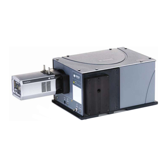
SECTION 1 - INTRODUCTION Shamrock SR-303i Base Unit Firstly thank you for choosing the Andor Shamrock SR-303i. We appreciate you have a choice and are delighted you have selected our equipment to fulfil your requirements. The Shamrock SR-303i is available in two types: 1. -
Page 7: Working With The Users Guide
INFORMATION PROVIDED HEREIN. 1.3 - COPYRIGHT AND PROTECTIVE NOTICES 1. The copyright in this document and the associated drawings are the property of Andor Technology plc and all rights are reserved. This document and the associated drawings are issued on condition that they are not copied, reprinted or reproduced, nor their contents disclosed. -
Page 8: Technical Support
ABOUT THE SHAMROCK SR-303i 1.5 - TECHNICAL SUPPORT If you have any questions regarding the use of this equipment, please contact the representative* from whom your system was purchased or via one of the following addresses: Europe Andor Technology Andor Technology... -
Page 9: Components
ABOUT THE SHAMROCK SR-303i 1.6 - COMPONENTS The main components & accessories of the Andor Shamrock SR-303i system are shown on page 12. 1.7 - SPECIFICATIONS General Czerny-Turner arrangement with imaging toroidal optics Focal Length 303mm Aperture Reciprocal Dispersion 2.6nm/mm (nominal) Wavelength Range 190nm to 10µm (detector dependent) -
Page 10: Section 2 - Installation
NOTE: In the event of extreme power or ESD surges, the software may crash. Should this occur, power the SR-303i OFF/ON, then restart the software. 2.2 - UNPACKING THE SHAMROCK SR-303i BEFORE unpacking the SR-303i, allow the shipping box to fully acclimatise to room temperature. -
Page 11: Installing Hardware
INSTALLATION 2.3 - INSTALLING HARDWARE Carefully remove the SR-303i from its packaging. The following should be included: Shamrock SR-303i base unit • Universal power supply (with relevant lead and plug - country specific) • • Allen Key set comprising 2mm, 2.5mm, 3mm & 5mm keys C Cable •... -
Page 12: Accessories
INSTALLATION 2.4 - ACCESSORIES SR-303i SECTION 2 Page 12... -
Page 13: Usb Installation
INSTALLATION 2.5 - USB INSTALLATION The SR-303i has a USB interface which allows the system to be used as a standalone device, i.e., independent of an Andor CCD controller card. To install the USB drivers, firstly connect the USB cable to the computer and to the SR-303i. A Hardware wizard will then guide the user through the USB drivers’... -
Page 14: Windows 2000 Hardware Wizard
INSTALLATION 2.5.1 - Windows 2000 Hardware Wizard 1. When the USB cable is connected to a PC running Windows 2000 and the SR303i is then powered on, the following Found New Hardware Wizard dialog box should appear: 2. Click Next> and the following dialog box should appear: 3. - Page 15 INSTALLATION 4. The following dialog box should appear: 5. Tick the Specify a location option then click Next>. The following dialog box should appear: 6. Click Browse… to go to the correct location for the file dev03edb.inf, e.g.: 7. Select the file click Open, then OK. SR-303i SECTION 2 Page 15...
- Page 16 INSTALLATION 8. If the driver is successfully located, the following dialog box should appear: 9. Click Next> and the following dialog box should appear: 10. Click Finish to complete the driver installation. You can check that the “DeVaSys” USB device is recognised by checking system\hardware\device manager via the Control Panel option of the PC.
-
Page 17: Windows Xp Hardware Wizard
INSTALLATION 2.5.2 - Windows XP Hardware Wizard 1. When the USB cable is connected to a PC running Windows XP and the SR303i is powered on, the following Found New Hardware Wizard dialog box should appear: NOTE: If this dialog box does not appear, firstly check that the USB cable is securely connected. If that is OK then double-click on the “New unknown USB device”... - Page 18 INSTALLATION 2. When the dialog box is active, select the No, not this time option, e.g.: 3. Click Next> 4. A dialog box similar to the following should appear: 5. Select the Install from a list or specific location (Advanced) option then click Next>. A dialog box similar to the following should appear: 6.
- Page 19 INSTALLATION 7. The following dialog box should appear: 8. Click on the Next> button and the software should begin to install, e.g.: 9. After the software is installed, the following dialog box should appear: 10. Click Finish. The spectrograph software is now ready for use. SR-303i SECTION 2 Page 19...
-
Page 20: Note On Drivers
USB interface is not “Hot-Plugable”. Before installing the drivers carry out the following actions: Switch off the computer and the Shamrock SR-303i. • Connect the USB cable to the computer then to the Shamrock SR-303i. • Switch on the Shamrock SR-303i first then switch on the computer. •... -
Page 21: Disconnecting Or Reconnecting The Usb Interface
INSTALLATION 2.5.4 - Disconnecting or Reconnecting the USB Interface The USB can be disconnected or reconnected at any time, provided that the SR-303i software is not running. If you are using a SR-303i with serial number less than SR0045, then its USB connection is NOT ‘hot-pluggable’, and the following steps must be followed to disconnect/reconnect the USB: Double-click on the USB icon at the bottom-right of the screen. -
Page 22: Connecting The Camera To The Shamrock Sr-303I
INSTALLATION 2.6 - CONNECTING THE CAMERA TO THE SHAMROCK SR-303i The camera is connected to the SR-303i using the flange supplied with the product. This process varies depending on whether the user purchased a pre-aligned camera & spectrograph or a “standalone” spectrograph (i.e. -
Page 23: Standalone Spectrograph
INSTALLATION 2.6.2 - Standalone Spectrograph Where a “standalone” spectrograph (i.e. purchased without, or separately from, an Andor camera) has been purchased the unit is supplied with an appropriate camera flange to allow the camera to be attached to the spectrograph body. The camera must be attached to the flange and the flange attached to the spectrograph body with the screws supplied, e.g.: Figure 2: Attaching a camera to the SR-303i In this instance, the focusing tube is not pre-set before shipping, so the unit must be adjusted to achieve the... -
Page 24: Andor Pci Card Systems
INSTALLATION 2.7 - ANDOR PCI CARD SYSTEMS Figure 3 illustrates the connection details for a standard Andor PCI CCD camera. The PCI Controller Card should be installed as you would other slot-in cards, such as graphic or parallel printer adapter cards. Please consult the manual supplied with your PC to ensure correct installation of the Controller Card for your particular PC. -
Page 25: Usb Interface Detectors
INSTALLATION 2.8 - USB INTERFACE DETECTORS Figure 4 shows the electrical connections used when using the Shamrock SR-303i with an Andor iDus USB camera. Figure 4: Hardware connections (USB 2.0 CCD systems) SR-303i SECTION 2 Page 25... -
Page 26: Filter Wheel Installation (Part # Sr-Asz-7001)
INSTALLATION 2.8 - FILTER WHEEL INSTALLATION (PART # SR-ASZ-7001) The package containing the filter wheel should have the following items contained within: 6-position filter wheel assembly SR-ASZ-7001 (figure 5 below) • Filter ring wrench (part number MSC-00176) • Allen Key (4mm) •... -
Page 27: Installation Of The Filter Wheel Onto The Spectrograph Body
INSTALLATION 2.8.1 - Installation of the filter wheel onto the spectrograph body 1. Turn off the power to the spectrograph. Carefully tip the spectrograph body onto its side, then remove the PCB cover plate on the underside of the spectrograph and the motorised slit assembly: 2. -
Page 28: Update Of The Variables Stored In The Spectrograph Eeprom
INSTALLATION 2.8.2 - Update of the variables stored in the spectrograph EEPROM 1. Connect the spectrograph and start-up the Andor Solis software 2. Run the EEPROM modifier program saved on the stored CD (EEPROM SR-xxxx.pgm, where xxxx is the filter wheel serial number). Note: Some of the numbers are specific to each filter wheel and the label on the CD should match the serial number on the filter wheel label. -
Page 29: Installation Of Filters
INSTALLATION 2.9 - INSTALLATION OF FILTERS Filters may be added, removed or replaced in the filter wheel in two ways: Option 1: by the complete removal of the filter wheel from the filter wheel housing • • Option 2: via the filter access hole on the front face of the filter wheel housing 2.9.1 - Option 1 Option 1 may be found to be more convenient when a large number of filters are to be added at the same time, or prior to the initial installation of the filter wheel assembly onto the spectrograph body. -
Page 30: Initialising The Filter Wheel
INSTALLATION 2.9.2 - Option 2 Access to the filters may also be gained via the filter access hole located on the front face of the filter wheel. 1. Remove the magnetic filter wheel access cover by gently pulling it, i.e.: The filter position ID number will now be visible, e.g.: NOTE: The filter position accessible via the access hole has an ID number 2 less than the filter position in the optical path, and the number displayed in the software (e.g. -
Page 31: Filter Wheel Control And Updating The Filter Details Stored In The Spectrograph Memory
INSTALLATION 2.9.4 - Filter wheel control and updating the filter details stored in the spectrograph memory The optional filter wheel accessory is controlled by the Filter Wheel Control. This is described in more detail in on page 50. 1. The Filter Wheel Control indicates the currently selected filter and provides details of the filter at the bottom of the control. -
Page 32: Schematic Diagram Of The Filter Wheel Assembly
INSTALLATION 2.9.5 - Schematic diagram of the filter wheel assembly SR-303i SECTION 2 Page 32... -
Page 33: Dimensions & Specification Of The 6-Position Filter Wheel Assembly (Part # Sr-Asz-7001)
INSTALLATION 2.9.6 - Dimensions & specification of the 6-position filter wheel assembly (part # SR-ASZ-7001) Specifications Filter Size 1” Maximum number of filters Maximum filter thickness Maximum time between filter changes 2 secs SR-303i SECTION 2 Page 33... -
Page 34: Section 3 - Operation
You are firstly presented with the Shamrock SR-303i splash screen, indicating the software is specifically configured to control the SR-303i which in turn, automatically launches the Dashboard. The dialog... -
Page 35: Detector Controls
OPERATION 3.1 - DETECTOR CONTROLS The following paragraphs describe the basic camera controls incorporated on the Dashboard control. For more detailed descriptions of these parameters and other available adjustments please refer to the supplied camera manual. 3.1.1 - Exposure Time Control The Exposure Time Control (figure 7) can be set to any value between the minimum valid exposure time (detector dependent) and 3600 secs. -
Page 36: Read Mode Control
OPERATION 3.1.2 - Read Mode Control The Read Mode Control dialog box (figure 8) is located to the right of the Exposure control and can be used to change the way in which the information from the CCD in the camera is read. The mode is selected by clicking one of the buttons in the dialog box. -
Page 37: Spectrograph Controls
OPERATION 3.2 - SPECTROGRAPH CONTROLS 3.2.1 - Reset Menu Options When the <Reset button on the Reset Menu (figure 9) is clicked, you then have several options that allow you to reset the various mechanisms in the system. This may be found to be necessary if a mechanism setting appears to have deviated from the displayed value (e.g. -
Page 38: Wavelength Drive Control
OPERATION 3.2.2 - Wavelength Drive Control The wavelength drive hardware not only sets the system to the target wavelength but is also used to control grating selection. The Wavelength Drive Control (figure 10) is used for setting the wavelength range for the current grating. -
Page 39: Step And Glue Function
OPERATION 3.2.3 - Step and Glue Function The Step and Glue function allows to user to build up a composite spectrum made up of individual spectra. The user selects the start and wavelength of the scan region and the grating to be used. The software will then control the acquisition of several spectra that cover this spectral region. - Page 40 OPERATION There are now several new graphic features. The hatched slide control bar gives an indication of the current wavelength position and current active grating in the system. The Step and Glue slide bar control will also appear. the slider bar allows the user to enter the start and end wavelengths for the Step and Glue mode and select the grating with which to take the data.
- Page 41 OPERATION The scan is initiated by clicking the Take Signal button on the main Andor Solis toolbar. If the grating specified in the grating selection box is different from the currently set grating the system will first drive to the selected grating before commencing the scan.
-
Page 42: Grating Turret Control
OPERATION 3.2.4 - Grating Turret Control The Grating Turret Control (Figure 17) is used to select a new grating by rotating the grating turret to a new position. There are three turret positions available so that a maximum of three grating can be fitted at any one time. -
Page 43: Removing & Replacing The Grating Turret
OPERATION 3.3 - REMOVING & REPLACING THE GRATING TURRET 1. The SR-303i has a unique replaceable triple grating turret (figure 18). This section describes how to replace a previously fitted grating turret and also how to fit a new grating turret. NOTE: We strongly recommend protective gloves be worn to avoid damage to the gratings. -
Page 44: Fitting A New Grating Turret
OPERATION 3.4 - FITTING A NEW GRATING TURRET To fit a new turret, follow steps 1 - 5 for Removing and replacing the Grating Turret shown on the previous page. The grating parameters for the new turret must be inputted into the non-volatile memory (EEPROM) in the spectrograph. - Page 45 OPERATION 4. First select the turret number that this new turret shall be known by e.g. Turret 2 (T2). Next, input the number of gratings installed on the new grating turret. Figure 18 on page 43 illustrates the position order of the three gratings. The Grating 1 position is identified by the V-groove on the base of the turret. 5.
-
Page 46: Offset Adjustment Control
OPERATION 3.5 - OFFSET ADJUSTMENT CONTROL The Offset Adjustment Control (figure 19) allows the user to adjust the calibration of the instrument. We shall define two types of offset. A detector offset and a grating offset. Figure 19: Detector and Grating Offset Adjustment Control The Detector offset value can be adjusted to correct for any mechanical change that shifts (offsets) the displayed spectrum from the expected calibrated position. -
Page 47: Offset Adjustment Procedure
OPERATION 3.5.1 - Offset Adjustment Procedure Detector or grating offset adjustment is selected via the tabs on the Offset Adjustment Control. The following describes the procedure for the detector offset adjustment but the grating offset adjustments are performed in the same manner. 1. -
Page 48: Slit Drive Control
OPERATION 3.6 - SLIT DRIVE CONTROL The Slit Drive Control (figure 21) is used to control the Motorised Slit Assembly (see figure 32 on page 57). The slits are used to control the amount of incident light that enters the spectrograph. The width can be varied between 10µm and 2500µm (in steps of 2.5µm). -
Page 49: Filter Wheel Control
OPERATION 3.7 - FILTER WHEEL CONTROL The optional filter wheel accessory is controlled by the Filter Wheel Control: Figure 112: Filter Wheel Control The Filter Wheel Control indicates the currently selected filter and provides details of the filter at the bottom of the control. -
Page 50: Shutter Control
OPERATION 3.8 - SHUTTER CONTROL If you have a shutter attached to your system the Shutter Control can be used to set the shutter mode of operation: Figure 123: Shutter Control There are four modes of operation available: 1. Always Open: The shutter will be open before, during, and after any data acquisition. 2. -
Page 51: Control Of Shutter Via External Ttl Signal
OPERATION 3.8.1 - Control of Shutter via External TTL Signal For flexibility, the shutter in the SR-303i system may also be operated by an external TTL signal. This allows the shutter to be operated by, and synchronised to, other laboratory equipment. The shutter connector is a standard female BNC type and is located as shown in figure 24: Figure 134: External shutter connector NOTE: For correct shutter operation, via the shutter connector, it is first necessary to ensure that the... -
Page 52: Fitting A Shutter To The Shamrock Sr-303I
OPERATION 3.8.2 - Fitting a Shutter to the Shamrock SR-303i A shutter can be easily fitted or replaced by the user. Remove the 4off, M4 x 25mm cap-head screws attaching the 25mm thick spacer block to the body of the spectrograph (figure 25). It is not necessary to unplug the slit assembly ribbon cable. -
Page 53: Flipper Mirror Control
Flipper Mirror Control dialog. The selected port is highlighted in yellow and also identified below the graphic. Figure 28 shows a plan view of the various input and output ports on the Shamrock SR-303i Figure 157: Flipper Mirror Control NOTE: The Dual Exit Port option is not available as an accessory. -
Page 54: Accessory Port Control
The Accessory Port Control (figure 29) allows for simple control and communication with other electronic devices via the Shamrock SR-303i software interface. Two TTL compatible outputs are provided and can be controlled via the Accessory Port Control. The accessory connector is located on the side of the spectrograph (see figure 30 on page 56). -
Page 55: Appendix
APPENDIX APPENDIX A1.1 - MECHANICAL DRAWINGS A1.1.1 - Dimensions Note: Dimensions in mm (inches) Optical Axis 127mm [5”] with pad feet * The optical path height with standard feet attached as shown. The height with adjustable feet varies between 143mm [5.6”] and 173mm [6.8”] ** The overall length with a standard Andor model attached. -
Page 56: A1.1.2 - Electrical & Electronic Interface Connectors
APPENDIX A1.1.2 - Electrical & electronic interface connectors Figure 170: Connectors A1.1.3 - Entrance Port mounting details SR-303i SECTION 4 Page 56... -
Page 57: A1.1.4 - Motorised Slit Details (Part # Sr-Asz-0103)
APPENDIX A1.1.4 - Motorised Slit details (Part # SR-ASZ-0103) Figure 181: Motorised Slit Assembly SR-303i SECTION 4 Page 57... -
Page 58: A1.1.5 - Second Output Port (Port 2) Details (Model # Sr-303I-B Only)
APPENDIX A1.1.5 - Second Output Port (Port 2) details (Model # SR-303i-B only) SR-303i SECTION 4 Page 58... -
Page 59: A1.1.6- Alignment Of Optional Imaging Flange Accessory
APPENDIX A1.1.6- Alignment of optional Imaging Flange Accessory Figure 192 Imaging property of SR-303i at the imaging plane SR-303i SECTION 4 Page 59... -
Page 60: A1.1.7 - Accessory Connector Pin & Voltage Output Jumper Pin Details
APPENDIX A1.1.7 - Accessory Connector Pin & Voltage Output Jumper Pin details Figure 203: Accessory connector IMPORTANT NOTE: The output voltages are mainly intended for attachment of Andor designed accessories. Other devices should only be connected with caution. Maximum current values are 24V@200mA, 12V@100mA and 5V@100mA. Failure to observe these limits may damage the system. -
Page 61: A1.2- Terms & Conditions
‘GOODS’ means the goods (including any instalment of the goods or any parts for them) which the Seller is to supply in accordance with these Conditions. ‘SELLER’ means Andor Technology plc. ‘CONDITIONS’ means the standard terms and conditions of sale set out in this document and (unless the context otherwise requires) includes any special terms and conditions agreed in writing between the Buyer and Seller. -
Page 62: A1.3 - Warranties & Liability
APPENDIX A1.3 - WARRANTIES & LIABILITY 1. Subject to these Conditions set out below, the Seller warrants that the Goods will correspond with their specification at the time of delivery and will be free from defects in material and workmanship for a period of 12 months from the date of delivery. - Page 63 APPENDIX 6. Except in respect of death or personal injury caused by the Seller’s negligence, the Seller shall not be liable to the Buyer by reason of any representation (unless fraudulent), or any implied warranty, condition or other term, or any duty at common law, or under the express terms of the Contract, for any indirect, special or consequential loss or damage (whether for loss of profit or otherwise), costs, expenses or other claims for compensation whatsoever (whether caused by the negligence of the Seller, its employees or against otherwise) which arise out of or in connection with the supply of the Goods, or their use or resale by the Buyer and the...
Need help?
Do you have a question about the shamrock SR-303i and is the answer not in the manual?
Questions and answers