
Related Manuals for Oxford Instruments ANDOR iDus 416


Summary of Contents for Oxford Instruments ANDOR iDus 416
- Page 1 iDus 416 Version 1.2 revised 10 Oct 2024 Hardware Guide andor.com © Andor Technology 2024...
-
Page 2: Table Of Contents
iDus 416 TABLE OF CONTENTS SECTION 1: INTRODUCTION ....................... 8 INTRODUCTION ........................8 ABOUT THIS HARDWARE GUIDE ................... 8 SOLIS HELP ..........................8 TECHNICAL SUPPORT ......................9 DISCLAIMER ......................... 10 COPYRIGHT AND PROTECTIVE NOTICES ................10 TRADEMARKS AND PATENT INFORMATION ............... 10 SUPPLIED COMPONENTS .................... - Page 3 iDus 416 2.6.1 Air Cooling ........................ 18 2.6.2 Water Cooling......................18 2.6.3 Fan Settings ......................19 SECTION 3: INSTALLATION ....................... 20 COMPUTER REQUIREMENTS ....................20 INSTALLING THE CAMERA CONTROL SOFTWARE ............20 INSTALLING THE SOFTWARE & USB DRIVER ..............20 CONNECTING THE IDUS 416 TO A SPECTROGRAPH ............
- Page 4 iDus 416 SECTION 5: MAINTENANCE ......................25 CLEANING AND DECONTAMINATION .................. 25 REGULAR CHECKS ....................... 25 REPLACEMENT PARTS ......................25 FUSE REPLACEMENT ......................25 SECTION 6: TROUBLESHOOTING ....................26 UNIT DOES NOT SWITCH ON ....................26 DEVICE NOT RECOGNISED WHEN PLUGGED INTO PC............. 26 TEMPERATURE TRIP ALARM SOUNDS ................
-
Page 5: Revision History
iDus 416 Revision History Version Released Description Internal use only Initial version- developed from iDus 401/420 generic User Guide 19 Feb 2013 Internal use only Updated A2 Mechanical Dimensions to include with/without optional mounting foot information. 21 Feb 2013 Additional Safety Instructions added to Preface. Updated power supply Internal use only instructions and information, Section 1.7. -
Page 6: Safety And Warning Information
Before using the system, please follow and adhere to all warnings, safety, manual handling and operating instructions located either on the product or in this Hardware Manual The Andor iDus 416 is a precision scientific instrument containing fragile components. Always handle with care Do not expose the product to extreme hot or cold temperatures Ensure that a minimum clearance of approximately 90mm (3.5”) is maintained in front of all ventilation slots and... - Page 7 iDus 416 arning abeLs and ymboLs The following labels and symbols are found on the product and in the supplied User Guides: WARNING: Important safety information to ensure safe operation of the product. This product requires a DC power supply. Version 1.2 rev 10 Oct 2024...
-
Page 8: Section 1: Introduction
1.1 i ntroduction Thank you for choosing the Andor iDus 416. Andor’s CCD (Charge Coupled Device) exploits the processing power of today’s desk-top computers. USB 2.0 connectivity ensures a seamless interface with the camera, as well as generating and receiving the signals you use to work with pulsed sources. -
Page 9: Technical Support
iDus 416 INTRODUCTION 1.4 t echnical upport If you have any questions regarding the use of this equipment, please contact the representative* from whom your system was purchased, or: Europe Andor Technology Andor Technology 7 Millennium Way 425 Sullivan Avenue Springvale Business Park Suite # 3 Belfast... -
Page 10: Disclaimer
Andor and the Andor logo are trademarks of Andor Technology. Andor Technology is an Oxford Instruments company. All other marks are property of their owners. Changes are periodically made to the product and these will be incorporated into new editions of the manual. New versions of all Andor manuals will be made available through MyAndor http://my.andor.com/login.aspx. -
Page 11: Supplied Components
iDus 416 INTRODUCTION 1.8 S upplied omponentS The standard components are outlined below. Please refer to the packing list and your order information to ensure that your camera and system options are present. Description Quantity iDus 416 CCD Camera USB 2.0 Cable Power Supply Unit (PSU) and Country Specific Power Cord BNC-SMB Cable Allen Key (x2) -
Page 12: Optional Components
iDus 416 INTRODUCTION 1.9 o ptional omponentS There are a range of optional components available including: • Spectrographs such as Andor Shamrock and HoloSpec series • Control Software e.g. Solis and SDK2 • Water Cooling systems (re-circulator or chiller) and accessories •... -
Page 13: Section 2: Product Overview
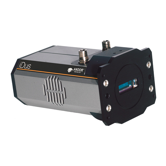
iDus 416 INTRODUCTION SECTION 2: PRODUCT OVERVIEW This section provides an overview of the iDus 416. 2.1 h ardWare eatureS Water Pipe Connectors CCD Sensor (for optional water cooling) Camera Window Power and Signal Connections (on back plate) UltraVac Cooling Fan (ventilation slots must be kept clear) Mounting Flange Figure 1: Main features of the iDus 416... -
Page 14: Power And Signal Connections
iDus 416 INTRODUCTION ooling When running in normal air-cooled mode a cooling fan is used to dissipate heat from the sensor TEC. It is important to ensure that the ventilation slots on each side of the camera are kept clear of obstruction for effective cooling. For further information refer to Sections 2.5 and 2.6. - Page 15 iDus 416 INTRODUCTION uSb 2.0 c onnection A USB 2.0 compatible cable can be connected between the USB socket and a PC to enable control of the camera. onnection The pin connections for the five-way I C connector used on the iDus are shown below: FUNCTION SHUTTER (TTL) C CLOCK...
-
Page 16: Power Supply
iDus 416 INTRODUCTION 2.2 p oWer upply The iDus 416 is supplied with an external PSU with a 5 pin DIN output plug. Do not use any other power supply unit with the iDus 416 other than those specified by Andor. The external power supply requirements are: 100-240 VAC, 50-60 Hz. •... -
Page 17: Working With Electronics
iDus 416 2.4 W orking With lectronicS The computer equipment that is to be used to operate the iDus 416 should be fitted with appropriate surge/EMI/RFI protection on all power lines. Dedicated power lines or line isolation may be required for some extremely noisy sites. Appropriate static control procedures should be used during the installation of the system. -
Page 18: Cooling
iDus 416 2.6 c ooling The CCD detector is cooled using a thermoelectric (TE) cooler. TE coolers are small, electrically powered devices with no moving parts, making them reliable and convenient. A TE cooler is actually a heat pump, i.e. it achieves a temperature difference by transferring heat from its ‘cold side’... -
Page 19: Fan Settings
iDus 416 WARNINGS • NEVER USE COOLING WATER THAT IS COLDER THAN THE DEW POINT OF THE AIR IN THE ROOM. DAMAGE CAUSED IN THIS WAY IS NOT COVERED BY THE WARRANTY. • RECOMMENDED COOLING SUPPLY PRESSURE: MAX 2 BAR (30 PSI) NOTES: •... -
Page 20: Section 3: Installation
iDus 416 INSTALLATION SECTION 3: INSTALLATION 3.1 c omputer equirementS The minimum computer requirement for correct iDus operation is as follows: • 3.0GHz single core or 2.4GHz multi core Processor with 2GB RAM • Windows (XP, Vista, 7 or 8) or Linux •... -
Page 21: Connecting The Idus 416 To A Spectrograph
iDus 416 INSTALLATION 3.4 c onnecting the i to a pectrograph Notes: • Refer also to your Spectrograph User Guide. • If an Andor Spectrograph was ordered with your iDus 416, the iDus 416 should come ready to use and aligned on the Spectrograph. -
Page 22: Connecting The Signal Cables Between The Idus 416 And The Spectrograph
iDus 416 INSTALLATION 3.4.2 c onnecting the ignal ableS betWeen the i and the pectrograph The Spectrograph can be controlled through either the SMB or I C (where available) connections. Both options are shown below: 3.4.2.1 Smb Connect the SMB to BNC cable to the camera SMB Shutter connection. Connect the other end of the SMB to BNC cable to the Spectrograph Shutter BNC connection. -
Page 23: Connecting The Idus 416 To The Control Pc
iDus 416 INSTALLATION 3.5 c onnecting the i to the ontrol Ensure the mains power cable is not inserted before attaching the PSU to the camera. Insert the power cable from the power supply into the 5-way DIN power connector at the rear of the camera. Secure in position using the screw-lock. -
Page 24: Section 4: Using The Idus 416
iDus 416 Using the iDus 416 SECTION 4: USING THE IDUS 416 The iDus 416 is controlled through the software and the options and functions available will depend on which software is used. Please refer to your control software e.g. Solis or SDK2. WARNINGS: •... -
Page 25: Section 5: Maintenance
iDus 416 MAINTENANCE SECTION 5: MAINTENANCE WARNINGS: • THERE ARE NO USER MAINTENANCE PROCEDURES REQUIRED FOR THE IDUS 416. • THE SYSTEM SHOULD BE POWERED-DOWN PRIOR TO USER PERFORMING ANY SYSTEM CHECKS. • DO NOT USE EQUIPMENT THAT IS DAMAGED. •... -
Page 26: Section 6: Troubleshooting
iDus 416 TROUBLESHOOTING SECTION 6: TROUBLESHOOTING 6.1 u nit doeS not SWitch on • Check power cord is plugged in and connected correctly to mains supply • If applicable, replace fuse in the supplied mains cable (Section 5.4). • If the unit still does not switch on after the checks above have been carried out, contact Andor Technical Support 6.2 d evice not recogniSed When plugged into... -
Page 27: Section 7: Technical Specifications
iDus 416 TECHNICAL SPECIFICATIONS SECTION 7: TECHNICAL SPECIFICATIONS 7.1 g eneral Model Standard Cooling: Deep Cooling: DV416A-LDC-DD DU416A-LDC-DD Sensor LDC-DD: Back-Illuminated CCD, Deep-Depletion with anti-fringing, low dark current Active pixels 2000 x 256 Pixel size (W x H) 15 x 15 μm Image area 30 x 3.8 mm Register well depth (typical) -
Page 28: Appendix A: Mechanical Drawings
iDus 416 MECHANICAL DRAWINGS APPENDIX A: MECHANICAL DRAWINGS Dimensions in mm [inches] Third-angle projection = position of pixel 1,1 Weight: 2 kg [4 lb 8 oz] Mounting hole locations NOTE: There are 2x holes: 1x on top and 1x on the bottom of the camera Rear connector panel Version 1.2 rev 10 Oct 2024... -
Page 29: Appendix B: Glossary
iDus 416 GLOSSARY APPENDIX B: GLOSSARY If this is the first time you have used an Andor CCD camera, the glossary that follows will help familiarize you with its design philosophy and some of its key terminology. B1.1 - CCD A Charge Coupled Device (CCD) is a silicon-based semiconductor chip bearing a two-dimensional matrix of photo- sensors, or pixels. - Page 30 iDus 416 GLOSSARY B1.1.1 - r eadout equence of a In the course of readout, charge is moved vertically into the shift register, and then horizontally from the shift register into the output node of the amplifier. The readout sequence illustrated below (which corresponds to the default setting of the Full Resolution Image binning pattern) allows data to be recorded for each individual element on the CCD-chip.
- Page 31 iDus 416 GLOSSARY B1.4 - a/d c onverSion Charge from the CCD is initially read as an analog signal, ranging from zero to the saturation value. A/D (Analog to Digital) conversion changes the analog signal to a binary number which can then be manipulated by the computer. B1.5 - b ackground Background is a data acquisition made in darkness.
- Page 32 iDus 416 GLOSSARY The example below illustrates readout of data from adjacent tracks, each track comprising two binned rows of the CCD- chip. Exposure to light causes a pattern of charge (an electronic image) to build up on the frame (or Image Area) of the CCD-chip. Charge in the frame is shifted vertically by one row, so that the bottom row of charge moves down into the shift register.
- Page 33 iDus 416 GLOSSARY B1.7 - c ountS Counts refer to the digitization by the A/D conversion and are the basic unit in which data are displayed and processed. Depending on the particular version of the detection device, one count may, for example, be equated with a charge of 10 photoelectrons on a pixel of the CCD.
- Page 34 iDus 416 GLOSSARY B1.11 - f rame ranSfer Frame transfer is a mode of operation of the chip. It can be switched on for any acquisition mode. It is only available if your system contains a Frame Transfer CCD (FT CCD). This mode is not applicable to the iDus 416. An FT CCD differs from a standard CCD in 2 ways: Firstly, an FT CCD contains 2 areas, of approximately equal size (see figure below).
- Page 35 iDus 416 GLOSSARY Shot noise cannot be removed because it is due to basic physical laws. Most simply defined, shot noise is the square root of the signal (or dark signal) measured in electrons. B1.12.1.1 - r eadout oiSe Readout noise (which in our cameras is, in any case, low) is due to the amplifier and electronics: it is independent of dark signal and signal levels;...
- Page 36 iDus 416 GLOSSARY B1.13 - p ixel A Pixel is an individual photosensor (or element) on a CCD. B1.14 - q uantum fficiency pectral eSponSe The glossary refers to signals as a number of electrons. More strictly speaking these are ‘photoelectrons’, created when a photon is absorbed.
-
Page 37: Appendix C: Ccd Technology
iDus 416 CCD TECHNOLOGY APPENDIX C: CCD TECHNOLOGY This section provides some further information on the technology that is used in Andor CCD cameras such as the iDus 416. Vacuum Housing Unless protected, cooled CCD sensors will condense moisture, hydrocarbons and other gas contaminants that will attack the CCD surface. -
Page 38: Appendix D: Dew Point Graph
iDus 416 DEW POINT APPENDIX D: DEW POINT GRAPH The graph below plots the relationship between Relative Humidity and Dew Point at varying ambient temperatures. This can be used to calculate the minimum temperature the cooling water should be set to. In the relatively dry atmosphere of an air-conditioned lab, cooling water at 10ºC should not present any problems. -
Page 39: Appendix E: Other Information
iDus 416 OTHER INFORMATION APPENDIX E: OTHER INFORMATION erms and ondiTions of ale and arranTy nformaTion The terms and conditions of sale, including warranty conditions, will have been made available during the ordering process. The current version may be viewed at: http://www.andor.com/pdfs/literature/Andor_Standard_Warranty.pdf 2006 (Weee) asTe...
Need help?
Do you have a question about the ANDOR iDus 416 and is the answer not in the manual?
Questions and answers