Table of Contents
Advertisement
Advertisement
Table of Contents

Related Manuals for MSI 945G Neo2 Series


Summary of Contents for MSI 945G Neo2 Series
- Page 1 945P/G/PL Neo2 Series MS-7176 (v2.X) ATX Mainboard G52-M7176XG...
- Page 2 FCC-B Radio Frequency Interference Statement This equipment has been tested and found to comply with the limits for a class B digital device, pursuant to part 15 of the FCC rules. These limits are designed to provide reasonable protection against harmful interference in a residential installation. This equipment generates, uses and can radiate radio frequency energy and, if not installed and used in accordance with the instruction manual, may cause harmful interference to radio communications.
-
Page 3: Copyright Notice
This device complies with Part 15 of the FCC Rules. Operation is subject to the following two conditions: (1) this device may not cause harmful interference, and (2) this device must accept any interference received, including interference that may cause undesired operation Copyright Notice The material in this document is the intellectual property of MICRO-STAR INTERNATIONAL. -
Page 4: Technical Support
Alternatively, please try the following help resources for further guidance. † Visit the MSI homepage & FAQ site for technical guide, BIOS updates, driver updates, and other information: http://www.msi.com.tw & http://www.msi. -
Page 5: Weee Statement
WEEE Statement... -
Page 8: Table Of Contents
CONTENTS FCC-B Radio Frequency Interference Statement ............ii Copyright Notice ....................... iii Technical Support ..................... iv Safety Instructions ....................iv WEEE Statement ......................v English ......................E-1-1 Chapter 1. Getting Started ................E-1-3 Mainboard Specifications ................E-1-4 Mainboard Layout ..................E-1-6 Packing Contents .................. - Page 9 Front Panel Connectors: JFP1 / JFP2 ..........E-2-17 Front USB Connectors: JUSB1 / JUSB2 ..........E-2-18 Front Panel Audio Connector: JAUD1 ..........E-2-18 IrDA Infrared Module Header: JIR1 ............. E-2-19 Serial Port Connector: JCOM1 ............E-2-19 D-Bracket™ 2 Connector: JDB1 ............E-2-20 FWH/LPC Debugging Pin Header: JLPC1 ...........
- Page 10 Mémoire ......................F-13 Installation de Modules DDR2 ............... F-13 Setup du BIOS ....................F-15 Cell Menu ...................... F-17 Deudsth ....................... G-1 Chapter 1. Getting Started ................G-3 Spezifikationen des Mainboards ..............G-5 Mainboard Layout ..................G-7 CPU & Kühler Eibau ..................G-9 Einführung zu DDR2 SDRAM ...............
-
Page 11: English
945P/G/PL Neo2 Series User’s Guide English... -
Page 12: Chapter 1. Getting Started
Chapter 1. Getting Started Getting Started Thank you for choosing the 945P/G/PL Neo2 Series(MS- 7176) v2.x ATX mainboard. The 945P/G/PL Neo2 Series mainboard is based on Intel 945P/G/PL and Intel ICH7/ICH7R chipset for ® ® optimal system efficiency. Designed to fit the advanced Intel ®... -
Page 13: Mainboard Specifications
Supports 3/4 pin CPU Fan Pin-Header with Fan Speed Control. † Supports up to Pentium 4 3XX, 5XX, 6XX & P4EE (Intel Pentium 4 Processor † with HT Technology Extreme Edition). (For the latest information about CPU, please visit http://www.msi.com.tw/program/ products/mainboard/mbd/pro_mbd_cpu_support.php) Chipset Intel 945P/G/PL chipset †... - Page 14 Getting Started On-Board IDE One Ultra DMA 66/100 IDE controllers integrated in ICH7/ICH7R. † - Supports PIO, Bus Master operation modes. - Can connect up to Six Ultra ATA drives. SATAII controller integrated in ICH7/ICH7R. † - Up to 300MB/sec transfer speed. - Can connect up to four SATAII devices.
-
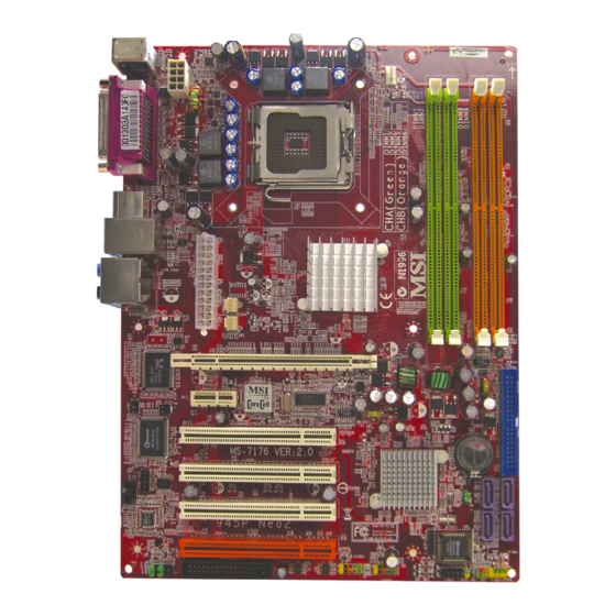
Page 15: Mainboard Layout
MS-7176 ATX Mainboard Mainboard Layout JPW1 Top : mouse CPUFAN1 Bottom: keyboard Top : Parallel Port Bottom: COM portA VGA port (945G) ports Intel Top: LAN Jack 945P/G/PL Bottom: USB ports Line-In PWRFAN1 Li ne-Out T:RS-Out M:CS-Out B:SPDIFOut SYSFAN1 PCI_E1 RTL8110SB PCI_E2 JCI1... -
Page 16: Packing Contents
Getting Started Packing Contents MSI Driver/Utility CD SATA Cable *2 MSI motherboard D-Bracket 2 Standard Cable for Power Cable (Optional) IDE Devices Standard Cable for User’s Guide Back IO Shield Floppy Disk * The pictures are for reference only and may vary from the packing contents of the product you purchased. -
Page 17: Chapter 2. Hardware Setup
Hardware Setup Chapter 2. Hardware Setup Hardware Setup This chapter tells you how to install the CPU, memory modules, and expansion cards, as well as how to setup the jumpers on the mainboard. Also, it provides the instructions on connecting the periph- eral devices, such as the mouse, keyboard, etc. -
Page 18: Quick Components Guide
MS-7176 ATX Mainboard Quick Components Guide JPW1, p2-9 CPU,p2-3 CPUFAN1 DIMM1~4,p2-7 Back Panel, p2-10 ATX1,p2-9 PWRFAN1 SYSFAN1, p2-14 PCI-E1~2, p2-24 IDE1, p2-15 JIR1, p-2-19 JCI1, p2-23 JBAT1, p2-23 PCI1~4, p2-25 JCOM1, p2-19 JCD1, p2-17 SATA1~4, p2-16 JFP2, p2-17 JAUD1, p2-18 FDD1, p2-14 JFP1, p2-17 JDB1, p2-20... -
Page 19: Central Processing Unit: Cpu
If you do not have the CPU cooler, contact your dealer to purchase and install them before turning on the computer. For the latest information about CPU, please visit http://www.msi.com.tw/ program/products/mainboard/mbd/pro_mbd_cpu_support.php. MSI Reminds You... -
Page 20: Cpu & Cooler Installation
CPU Clip to clip the CPU up, pressing the clips on both sides to the center, as the arrows shown. MSI Reminds You... 1. Confirm if your CPU cooler is firmly installed before turning on your system. - Page 21 Hardware Setup 5. The CPU has a plastic cap on it to 6. Remove the cap from lever hinge side protect the contact from damage. (as the arrow shows). The pins of Before you have installed the CPU, socket reveal. always cover it to protect the socket pin.
- Page 22 CPU. MSI Reminds You... 1. Check the information in PC Health Status of H/W Monitor in BIOS (Chapter 3) for the CPU temperature. 2. Whenever CPU is not installed, always protect your CPU socket pin with the plastic cap covered (shown in Figure 1) to avoid damaging.
-
Page 23: Memory
DDR2 memory module in the DDR2 slot (DIMM1~DIMM4). Otherwise, you are not able to boot up your system and your mainboard might be damaged. For the updated supporting memory modules, please visit http://www.msi. com.tw/program/products/mainboard/mbd/pro_mbd_trp_list.php. DIMM1,2 and DIMM3,4 (from left (Green) to right(Orange)) Channel A (DIMM1 &... -
Page 24: Installing Ddr2 Modules
256MB~1GB 256MB~1GB 256MB~1GB 1GB~4GB MSI Reminds You... - Dual-channel DDR works ONLY in the 5 combinations listed in the table shown in the previous page. - Please select the identical memory modules to install on the dual channel, and DO NOT install three memory modules on three DIMMs, or it may cause some failure. -
Page 25: Power Supply
+12V +12V JPW1 MSI Reminds You... 1. These two connectors connect to the ATX power supply and have to work together to ensure stable operation of the mainboard. 2. Power supply of 350 watts (and above) is highly recommended for system stability. -
Page 26: Mouse/Keyboard Connector
MS-7176 ATX Mainboard Back Panel The back panel provides the following connectors: RS-Out L-In Parallel M ouse USB Ports CS-Out COM Port VGA Port L-Out Keyboard (945G Only) SPDIF Mouse/Keyboard Connector ® The mainboard provides a standard PS/2 mouse/keyboard mini DIN connector ®... -
Page 27: Serial Port Connector: Com Port
Hardware Setup Serial Port Connector: COM Port The mainboard offers one 9-pin male DIN connector COM Port. It’s a 16550A high speed communication port that send/receive/ 16 bytes FIFOs. You can attach a serial mouse or other serial device directly to it. Pin Definition SIGNAL DESCRIPTION... -
Page 28: Lan (Rj-45) Jack
(Surround R/L) (in 7.1 CH) Center/Subwoofer Line Out Speaker Out (Front R/L) ( in 7.1CH / 5.1CH) SPDIF-Out MSI Reminds You... For the advanced functions of the audio codec, please refer to Chapter 6,7: Introduction to Realtek ALC850/ALC880 for details. E-2-12... -
Page 29: Parallel Port Connector: Lpt1
Hardware Setup Parallel Port Connector: LPT1 The mainboard provides a 25-pin female centronic connector as LPT. A parallel port is a standard printer port that supports Enhanced Parallel Port (EPP) and Ex- tended Capabilities Parallel Port (ECP) mode. Pin Definition SIGNAL DESCRIPTION STROBE... -
Page 30: Floppy Disk Drive Connector: Fdd1
S e n s o r Control PWRFAN1 SYSFAN1 C P U F A N 1 MSI Reminds You... 1. Always consult the vendors for proper CPU cooling fan. 2. CPUFAN1 supports the fan control. Fan/heatsink with 3 or 4 fins are both available. ®... -
Page 31: Hard Disk Connector: Ide1
IDE1 can connect a Master and a Slave drive. You must configure second hard drive to Slave mode by setting the jumper accordingly. MSI Reminds You... If you install two hard disks on cable, you must configure the second drive to Slave mode by setting its jumper. Refer to the hard disk documentation supplied by hard disk vendors for jumper setting instructions. -
Page 32: Serial Ataii Connectors
Take out the dust cover and connect to the hard disk devices Connect to serial ATA ports MSI Reminds You... Please do not fold the serial ATA cable in a 90-degree angle, since this might cause the loss of data during the transmission. E-2-16... -
Page 33: Cd-In Connector: Jcd1
Hardware Setup CD-In Connector: JCD1 The connector is for CD-ROM audio connector. JCD1 Front Panel Connectors: JFP1 / JFP2 The mainboard provides two front panel connectors for electrical connection ® to the front panel switches and LEDs. JFP1 is compliant with Intel Front Panel I/O Connectivity Design Guide. -
Page 34: Front Usb Connectors: Jusb1 / Jusb2
USB1+ JUSB1 / JUSB2 (USB 2.0/standard spec) USBOC MSI Reminds You... Note that the pins of VCC and GND must be connected correctly, or it may cause some damage. Front Panel Audio Connector: JAUD1 The F_AUDIO front panel audio connector allows you to connect to the front ®... -
Page 35: Irda Infrared Module Header: Jir1
Hardware Setup IrDA Infrared Module Header: JIR1 The connector allows you to connect to IrDA Infrared module. You must con- figure the setting through the BIOS setup to use the IR function. JIR1 is compliant with ® Intel Front Panel I/O Connectivity Design Guide. Pin Definition JIR1 Signal... -
Page 36: D-Bracket™ 2 Connector: Jdb1
MS-7176 ATX Mainboard D-Bracket™ 2 Connector: JDB1 The mainboard comes with a JDB1 connector for you to connect to D-Bracket™ 2. D-Bracket™ 2 is a USB Bracket that supports both USB1.1 & 2.0 spec. It integrates four LEDs and allows users to identify system problem through 16 various combina- tions of LED signals. - Page 37 Hardware Setup Description D-Bracket™ 2 System Power ON The D-LED will hang here if the processor is damaged or not installed properly. Early Chipset Initialization Memory Detection Test Testing onboard memory size. The D-LED will hang if the memory module is damaged or not installed properly. Decompressing BIOS image to RAM for fast booting.
-
Page 38: Fwh/Lpc Debugging Pin Header: Jlpc1
MS-7176 ATX Mainboard D-Bracket™ 2 Description Testing Base and Extended Memory Testing base memory from 240K to 640K and extended memory above 1MB using various patterns. Assign Resources to all ISA. Initializing Hard Drive Controller This will initialize IDE drive and controller. Initializing Floppy Drive Controller This will initialize Floppy Drive and controller. -
Page 39: Jumpers
JBAT1 Keep Data Clear Data MSI Reminds You... You can clear CMOS by shorting 2-3 pin while the system is off. Then return to 1-2 pin position. Avoid clearing the CMOS while the system is on; it will damage the mainboard. -
Page 40: Slots
MS-7176 ATX Mainboard Slots The mainboard provides a PCI Express x16 slot, a PCI Express x1 slot and four 32-bit PCI bus slots. PCI Express Slots (optional) The PCI Express slots, as a high-bandwidth, low pin count, serial, intercon- nect technology, support Intel highest performance desktop platforms utilizing the Intel Pentium 4 processor with HT Technology. -
Page 41: Pci (Peripheral Component Interconnect) Slots
Hardware Setup PCI (Peripheral Component Interconnect) Slots The PCI slots allow you to insert the expansion cards to meet your needs. When adding or removing expansion cards, make sure that you unplug the power supply first. Meanwhile, read the documentation for the expansion card to make any necessary hardware or software settings for the expansion card, such as jumpers, switches or BIOS configuration. -
Page 42: Chapter 3. Bios Setup
SETUP. ² You want to change the default settings for customized features. MSI Reminds You... 1. The items under each BIOS category described in this chapter are under continuous update for better system performance. Therefore, the description may be slightly different from the latest BIOS and should be held for reference only. -
Page 43: Entering Setup
MS-7176 ATX Mainboard Entering Setup Power on the computer and the system will start POST (Power On Self Test) process. When the message below appears on the screen, press <DEL> key to enter Setup. Also you can press <F8> to enter boot menu. Press DEL to enter SETUP If the message disappears before you respond and you still wish to enter Setup, restart the system by turning it OFF and On or pressing the RESET button. - Page 44 BIOS Setup MSI Reminds You... The items under each BIOS category described in this chapter are under continuous update for better system performance. Therefore, the description may be slightly different from the latest BIOS and should be held for reference only.
-
Page 45: The Main Menu
MS-7176 ATX Mainboard The Main Menu Once you enter AwardBIOS CMOS Setup Utility, the Main Menu will appear on the screen. Use arrow keys to move among the items and press <Enter> to enter the sub-menu. Standard CMOS Features Use this menu for basic system configurations, such as time, date etc. Advanced BIOS Features Use this menu to setup the items of Award special enhanced features. - Page 46 BIOS Setup Load Fail-Safe Defaults Use this menu to load the default values set by the BIOS vendor for stable system performance. Load Optimized Defaults Use this menu to load the default values set by the mainboard manufacturer specifically for optimal performance of the mainboard. BIOS Setting Password Use these two menus to set the passwords for BIOS.
-
Page 47: Standard Cmos Features
MS-7176 ATX Mainboard Standard CMOS Features The items in Standard CMOS Features Menu includes some basic setup items. Use the arrow keys to highlight the item and then use the <+> or <-> keys to select the value you want in each item. Date (MM:DD:YY) This allows you to set the system to the date that you want (usually the current date). - Page 48 BIOS Setup Type This item allows you to select how to define the HHDD parameters. LBA/Large Mode This item allows you to enable or disable the LBA (Logical Block Address, the logical block size in hard disk) mode. Setting options: [Auto], [Disabled]. Block (Multi-Sector Transfer) Select Auto for a hard disk performance.
-
Page 49: Advanced Bios Features
MS-7176 ATX Mainboard Advanced BIOS Features Quick Boot Setting the item to [Enabled] allows the system to boot within 5 seconds since it will skip some check items. Available options: [Enabled], [Disabled]. CPU Configuration Press <Enter> to enter the sub-menu. **CPU Information** Manufacturer/Frequency/FSB Speed/Cache L1/Cache L2 The three items show the CPU related information of your system (read only). - Page 50 BIOS Setup Adjacent Cache Line Prefetch This item allows you to enable/disable the adjacent cache line prefetch mode. When disabled, only one 64 byte line from the 128 byte sector is prefetched (which contains the requested data). When enabled – both lines are prefetched no matter whether they have or have not the requested data.
-
Page 51: Advanced Chipset Features
MS-7176 ATX Mainboard Advanced Chipset Features MSI Reminds You... Change these settings only if you are familiar with the chipset. DRAM Frequency Use this field to configure the clock frequency of the installed DRAM. Setting options: [Auto], [400], [533], [667]. - Page 52 BIOS Setup PEG Port This item enables or disables the PEG (PCI Express Graphic) port function. Setting options: [Enabled], [Disabled]. PEG Force X1 This setting determines whether the PCI Express x16 graphic is used. When setting to Enabled, force the bandwidth frome x16 down to x1. Setting options: [Enabled] and [Disabled].
-
Page 53: Integrated Peripherals
MS-7176 ATX Mainboard Integrated Peripherals USB Functions This setting is used to enable/disable the onboard USB host controller. Setting options: [Disabled], [Enabled]. Port 64/60 Emulation This field allows you to enable or disable the USB Port 64/60 Emulation function. When the function is enabled, the USB keyboard is allowed to type some special combination keys. - Page 54 BIOS Setup Enhanced You can use two IDE devices and all of four SATA devices. Disabled Disable all IDE and SATA devices. Configure SATA as The item will appear when you select Enhanced mode in the “ATA/IDE Configura- tion” item. You can set the SATA mode in this item. Setting options are: RAID configure the SATA devices as RAID mode AHCI IDE...
-
Page 55: Power Management Features
MS-7176 ATX Mainboard Power Management Features MSI Reminds You... S3-related functions described in this section are available only when your BIOS supports S3 sleep mode. ACPI Aware O/S This item is to activate the ACPI (Advanced Configuration and Power Management Interface) Function. - Page 56 BIOS Setup Suspend Time Out (Minute) If system activity is not detected for the length of time specified in this field, all devices except CPU will be shut off. Settings: [Disabled], [1min], [2min], [4min], [8min], [10min], [20min], [30min], [40min], [50min], [60min]. Power Button Mode This feature allows users to configure the Power Button function.
- Page 57 MS-7176 ATX Mainboard Resume On PCI PME# When setting to [Enabled], this setting allows your system to be awakened from the power saving modes through any event on PME (Power Management Event). Setting options: [Disabled], [Enabled]. Resume On RTC Alarm This is used to enable or disable the feature of booting up the system on a scheduled time/date from the S3, S4, and S5 state.
-
Page 58: Pci/Pnp Resource Management
BIOS Setup PCI/PNP Resource Management This section describes configuring the PCI bus system and PnP (Plug & Play) feature. PCI, or Peripheral Component Interconnect, is a system which allows I/O devices to operate at speeds nearing the speed the CPU itself uses when communicating with its special components. - Page 59 MS-7176 ATX Mainboard IRQ 3/4/5/7/9/10/11/14/15 These items specify the bus where the specified IRQ line is used. The settings determine if AMIBIOS should remove an IRQ from the pool of available IRQs passed to devices that are configurable by the system BIOS. The available IRQ pool is determined by reading the ESCD NVRAM.
-
Page 60: H/W Monitor
BIOS Setup H/W Monitor This section shows the status of your CPU, fan, overall system status, etc. Monitor function is available only if there is hardware monitoring mechanism onboard. Chassis Intrusion The field enables or disables the feature of recording the chassis intrusion status and issuing a warning message if the chassis is once opened. -
Page 61: Cell Menu
MS-7176 ATX Mainboard Cell Menu The items here includes some important settings of CPU and PCI functions. MSI Reminds You... Change these settings only if you are familiar with the chipset. Adjust DDR Voltage (V) Adjusting the DDR voltage can increase the DDR speed. Any changes made to this setting may cause a stability issue, so changing the DDR voltage for long-term purpose is NOT recommended. - Page 62 [100]~[133] for needed frequency. CPU Dynamic OverClocking Dynamic Overclocking Technology is the automatic overclocking function, included in the MSI ’s newly developed CoreCell Technology. It is designed to detect the load balance of CPU while running programs, and to adjust the best CPU frequency automatically.
- Page 63 MS-7176 ATX Mainboard MSI Reminds You... 1. Even though the Dynamic Overclocking Technology is more stable than manual overclocking, basically, it is still risky. We suggest user to make sure that your CPU can afford to overclock regularly first. If you find the PC appears to be unstable or reboot incidentally, it's better to disable the Dynamic Overclocking or to lower the level of overclocking options.
-
Page 64: Load Fail-Safe/Optimized Defaults
BIOS Setup Load Fail-Safe/Optimized Defaults The two options on the main menu allow users to restore all of the BIOS settings to the default Fail-Safe or Optimized values. The Optimized Defaults are the default values set by the mainboard manufacturer specifically for optimal performance of the mainboard. -
Page 65: Bios Setting Password
MS-7176 ATX Mainboard BIOS Setting Password When you select this functions, a message as below will appear on the screen: Type the password, up to six characters in length, and press <Enter>. The password typed now will replace any previously set password from CMOS memory. You will be prompted to confirm the password. -
Page 66: Français
945P/G/PL Neo2 Séries Manual d’utilisation Français... -
Page 67: Chapter 1. Getting Started
Chapter 1. Getting Started Introduction Félicitation vous venez d’acheter les Séries 945P/G/PL Neo2 (MS-7176v2.X ATX .une carte mère excellente de MSI. les Séries 945P/G/PL Neo2 sont basées sur les chipsets Intel ® 945P/G/PL & ICH7/ICH7R pour obtenir un système performant. Destiné aux ®... -
Page 68: Spécificités De La Carte
Supporte 3/4 broche CPU ventilateur En-tête de broche avec le contrôle de † sa vitesse. Supporte jusqu’à Pentium 4 3XX, 5XX, 6XX & P4EE (Processeur Intel Pentium † 4 avec la HTTechnologie Extreme Edition). (plus d’information,visitez http://www.msi.com.tw/program/products/mainboard/mbd/ pro_mbd_cpu_support.php) Chipset Chipset Intel 945P/G/PL †... - Page 69 Introduction IDE Intégré Un contrôleurUltra DMA 66/100 IDE intégré dans ICH7/ICH7R. † - Supporte PIO, Bus Maître opératoires modes. - Peut connecter jusqu’aux six commandes d’Ultra ATA . Contrôleur Série ATAII intégré dans ICH7/ICH7R. † - Jusqu’à 300MB/sec de vitesses de transfert. - Peut connecter jusqu’à...
-
Page 70: Schéma De La Carte Mčre
La Carte Mère MS-7176 Schéma de la Carte Mère JPW1 Top : mouse CPUFAN1 Bottom: keyboard Top : Parallel Port Bottom: COM portA VGA port (945G) ports Intel Top: LAN Jack 945P/G/PL Bottom: USB ports Line-In PWRFAN1 Li ne-Out T:RS-Out M:CS-Out B:SPDIFOut SYSFAN1... - Page 71 Introduction Connecteur ATX 24-Pin Power : ATX1. Ce connecteur vous permet de vous connecter à une alimentation ATX. Connecteur ATX 12V Power : JPW1. Ce connecteur est utilisé pour con- necter à une alimentation 12V. Connecteur Floppy Disk Drive : FDD1. La carte mère procure un connecteur floppy disk drive standard supportant les floppy disk drives de 360K, 720K, 1.2M, 1.44M et 2.88M.
- Page 72 La Carte Mère MS-7176 Connecteur Front Panel Audio:JAUD1 Ce connecteur vous permet de connecter le panneau en façade audio. rDA Infrared : JIR1 Le connecteur vous permet En-têtes de Module de connecter le module infrarouge IrDA. Vous devez configurer la connexion par l’installation du BIOS pour utiliser la fonction IR.
-
Page 73: Installation De Cpu & Refroidissement
(comme le montre les flèches). MSI Vous Rappelle... 1. S’assurer que le ventilateur est bien installé avant de mettre en marche le système. 2. Ne pas toucher le socket CPU pour éviter de l’endommager. - Page 74 La Carte Mère MS-7176 5. Le socket CPU possède un plastique 6. Retirer la protection (comme indiqué de protection. Ne le retirer qu’au par al flèche), pour découvrir les moment d’installer le CPU. broches de contact. 7. Lever le levier et ouvrir le plateua de 8.
- Page 75 à nouveau et pousser sur correctement installé. le clip pour soulever le CPU. MSI Vous Rappelle... 1. Vérifier dans le BIOS les informations de température CPU dans : PC Health Status 2. lorsque le CPU n’est pas installé, protègent toujours votre broche de socket CPU avec le chapeau en plastique couvert (montré...
-
Page 76: Introduction De Ddr2 Sdram
DDR2 n’est pas compatible en arrière, vous devriez toujours installer le module de la mémoire DDR2 dans le slot DDR2 (DIMM1~DIMM4). Autrement, vous ne pouvez pas initialiser votre système, et peut-être la carte mère pourrait être endommagé. pour plus d’informations,visitez http://www.msi.com.tw/program/products/ mainboard/mbd/pro_mbd_trp_list.php. DIMM1~DIMM4 (de gauche verte à... -
Page 77: Installation De Modules Ddr2
256MB~1GB 256MB~1GB 256MB~1GB 1GB~4GB MSI Vous Rappelle... - Canal double DDR fonctionne SEULE MENT dans 5 combinasions listées dans la table sur la page précédente . - En mode à canal double, assurez-vous que vous installez des modules de mémoire du mêmes type et densité sur DDR DIMMs. -
Page 78: Setup Du Bios
La Carte Mère MS-7176 Panneau Arrière Le panneau arrière contient les connecteurs suivants: RS-Out L-In Parallèle Sourie USB Ports CS-Out COM Port VGA Port L-Out Clavier (945G Only) SPDIF Setup du BIOS Allumez votre ordinateur, le système lance le processus de POST (Power On Self Test). -
Page 79: Menu Principal
En choisissant cette option, le BIOS sera chargé avec les valeurs par défaut optimisées. MSI Vous Rappelle... Les articles de chaque catégorie de BIOS décrite en ce chapitre sont sous la mise à jour continue pour une meilleure exécution de système. - Page 80 La Carte Mère MS-7176 Integrated Peripherals Utilisez ce menu pour changer les choix relatifs aux périphériques intégrés. Power Management Setup Utilisez ce menu pour appliquer vos choix en ce qui concerne le power management PNP/PCI Configurations Apparaît si votre système supporte PNP/PCI. H/W Monitor Voir les statuts des CPU, ventilateur et système d’alarme.
-
Page 81: Cell Menu
Introduction Cell Menu Ce Chapitre inclus des paramètres importants sur le CPU, PCIE. MSI Vous Rappelle... Vous pouvez changer ces paramètres uniquement si vous êtes familiés avec le chipset. Adjust DDR Voltage (V) L’ajustement de la tension de DDR peut augmenter la vitesse de DDR. Tous les changements peuvent causer une issue stabile, donc le changement de la tension de DDR pour un long terme n’est pas recommandé. - Page 82 La Carte Mère MS-7176 Spread Spectrum Les cartes mères créent des EMI (Electromagnetic Interference). La fonction de Spread Spectrum réduit ces EMI. Si vous n’avez pas de problème d’EMI, laissez l’option sur Disabled, ceci vous permet une stabilité du système et des performances optimales. Dans le cas contraire, choisissez Enabled pour réduire les EMI.
- Page 83 Introduction MSI Vous Rappelle... 1. Même si la fonction de DOT est un overclocking plus stable, cela reste une opération risquée. Nous suggérons de vérifier que votre CPU peut supporter cet overclocking. Si le PC devient instable ou rebott, il est alors préférable de réduire le niveau d’overclocking ou de désactiver la fonction.
- Page 84 945P/G/PL Neo2 Series Benutzerhandbuch Deutsch...
-
Page 85: Chapter 1. Getting Started
Chapter 1. Getting Started Einleitung Danke, dass Sie das 945P/G/PL Neo2 Series(MS-7176) v2. x ATX Mainboard gewahlt haben. Das 945P/G/PL Neo2 Series Mainboard basiert auf dem Intel 945P/G/PL und Intel ® ® ICH7/ICH7R Chipsatz und ermoglicht somit ein optimales und effizientes System. Entworfen, um den hochentwickelten Intel ®... -
Page 86: Spezifikationen Des Mainboards
Unterstützt DDR2 533 Speicherschnittstelle. † Unterstützt DDR2 667 Speicherschnittstelle (945P/945G nur). † (Um den letzten Stand bezüglich der unterstützten Speichermodule zu erhalten, besuchen Sie bit te http://www.msi.com.tw/program/products/mainboard/mbd/ pro_mbd_trp_list.php.) Steckplätze Ein PCI Express x16 Slot. † Ein PCI Express x1 Slot. - Page 87 Einleitung On-Board IDE Ein im ICH7/ICH7R enthaltener Ultra DMA 66/100 IDE Kontroller. † - Unterstützt die Betriebsmodi PIO und Bus Mastering. - Bis zu sechs Ultra ATA Laufwerke anschließbar. Ein in den ICH7/ICH7R integrierter SATAII Kontroller. † - Übertragungsgeschwindigkeiten von bis zu 300MB/s. - Bis zu vier SATAII Laufwerke anschließbar.
-
Page 88: Mainboard Layout
MS-7176 ATX Mainboard Mainboard Layout JPW1 Top : mouse CPUFAN1 Bottom: keyboard Top : Parallel Port Bottom: COM portA VGA port (945G) ports Intel Top: LAN Jack 945P/G/PL Bottom: USB ports Line-In PWRFAN1 Li ne-Out T:RS-Out M:CS-Out B:SPDIFOut SYSFAN1 PCI_E1 RTL8110SB PCI_E2 JCI1... - Page 89 Einleitung ATX 24-Pin Stromanschluss: ATX1 Hier können Sie ein ATX Netzteil anschließen ATX 12V Stromanschluss: JPW 1 Diese Strom anschluss werden verwendet, um die Versorgung mit 12V Strom zu gewährleisten. Anschluss des Diskettenlaufwerks: FDD1 Das Mainboard verfügt über einen Standardanschluss für Diskettenlaufwerke mit 360 KB, 720 KB, 1,2 MB,1,44 MB oder 2,88 MB Kapazität.
- Page 90 MS-7176 ATX Mainboard Infrarotmodul Stifleiste: JIR1 Gestattet den Anschluss eines Infrarotmoduls. Sie müssen im BIOS die notwendigen Einstellungen vornehmen, um die IR Funktion nutzen zu können. JIR1 erfüllt die Anforderungen des “Intel Front Panel I/O Connectivity Design Guide”. Jumper zur CMOS Löschung: JBAT1Auf dem Mainboard gibt es einen sogenannten CMOS Speicher (RAM), der über eine Batterie gespeist wird und die Daten der Systemkonfiguration enthält.
-
Page 91: Cpu & Kühler Eibau
Sie die Klammern an beiden Seiten zur Mitte hin drücken, wie die Pfeile es anzeigen. MSI weist darauf hin... 1. Stellen Sie sicher, dass Ihr CPU Küler fest eingebaut ist, bevor Sie Ihr System anschalten. 2. Berühren Sie die Pins des CPU Sockels nicht, um Schaden zu vermeden. - Page 92 MS-7176 ATX Mainboard 5.Um die Kontakte vor Schäden zu 6. Entfernen Sie die Kappe von der Seite schützen, ist der CPU-Sockel auf des Hebelgelenks her (Wie der Pfeil der Oberseite mit einer Plastikkappe zeigt). Die Pins des Sockels werden versehen. Lassen Sie ihn stets frei gelegt.
- Page 93 Sie den Clip auf, um die CPU herauszuheben. MSI weist darauf hin... 1. Überprüfen Sie die Temperatur der CPU im “PC Health Status” im BIOS. 2. Schützen Sie die Pins des CPU Sockels stets vor Schaden (wie gezeigt in Schritt 5), indem Sie sie mit der Plastikkappe abdecken, immer wenn keine CPU installiert ist.
-
Page 94: Einführung Zu Ddr2 Sdram
DDR2 Sockel eingesetzt werden (DIMM1~DIMM4). Andernfalls können Sie Ihr System nicht hochfahren und können zudem Ihr Mainboard beschödigen. Um den letzten Stand bezüglich der unterstützten Speichermodule zu erhalten, besuchen Sie bitte http://www.msi.com.tw/program/products/mainboard/mbd/ pro_mbd_trp_list.php. DIMM1~DIMM4 (von links (Grün) nach rechts(Orange)) Kanal A (DIMM1 &... -
Page 95: Einbau Von Ddr2 Modulen
256MB~1GB 256MB~1GB 256MB~1GB 256MB~1GB 1GB~4GB MSI weist darauf hin... - Zweikanal DDR arbeitet NUR in den 5 zuvor aufgelisteten Kombinationen - Für den Eisatz im Zweikanalbetrieb, wählen Sie bitte identische Module und installieren Sie NICHT drei Speichermodule in drei Sockeln, da dies zu Fehlern führen kann. -
Page 96: Aufruf Des Bios Setup
MS-7176 ATX Mainboard Hinteres Anschlusspaneel Das hintere Anschlusspaneel verfügt über die folgenden Anschlüsse: RS-Out L-In Parallel Maus USB Ports CS-Out COM Port VGA Port L-Out Tastatur (945G Nur) SPDIF Aufruf des BIOS Setup Nach dem Einschalten beginnt der Computer den POST (Power On Self Test- Selbstüberprüfung nach Anschalten). - Page 97 Werkseinstellengen. Die Voreinstellung “Optimal Defaults” des BIOS stellt die besten Leistungseinstellungen für all Komponenten und das System zur Verfügung. MSI weist darauf hin... Die Menüpunkte jeder in diesem Kapitel beschriebenen BIOS Kategorie befinden sich in permanenter Weiterentwicklung um die Systemleistung zu verbessern.
- Page 98 MS-7176 ATX Mainboard Integrated Peripherals Verwenden Sie dieses Menü, um die Einstellungen für in das Board integrierte Peripheriegeräte vorzunehmen. Power Management Setup Verwenden Sie dieses Menü, um die Einstellungen für die Stromsparfunktionen vorzunehmen. PNP/PCI Configurations Dieser Eintrag erscheint, wenn Ihr System Plug und Play- Geräte am PCI-Bus unterstützt. H/W Monitor Dieser Eintrag gibt den Status der CPU, des Lufters, und generelle Warnungen zum Systemstatus wieder.
-
Page 99: Cell Menu
Einleitung Cell Menu Hier können Sie einige wichtige Einstellungen zu CPU und PCI Funktionen vornehmen. MSI weist darauf hin... Ändern Sie diese Einstellungen nur, wenn Sie mit diesem Chipsatz vertraut sind. Adjust DDR Voltage (V) Die Anpassung der DDR Spannung kann die DDR Geschwindigkeit erhöhen. Jegliche Änderung and diesen Einstellungen können zu Stabilitätsproblemen führen, deswegen... - Page 100 [100]~[133] wählen, je nach benötigter Frequenz. CPU Dynamic OverClocking Dynamic Overclocking Technology (D.O.T) ist die automatische Übertaktungsfunktion, die in MSI ’s neu entwickelter CoreCell Technologie enthalten ist. Sie dient zur Feststellung des Auslastungsgrades der CPU, während diese Programme abarbeitet, und passt die CPU-Frequenz automatisch an.
- Page 101 Einleitung MSI weist darauf hin... 1. Obgleich Dynamic Overclocking Technology stabiler ist als manuelles Übertakten, ist es dennoch grundsätzlich riskant. Es ist empfehlenswert zuerst sicher zu stellen, dass Ihre CPU eine regelmäßige Übertaktung verträgt. Sollten Sie feststellen, dass Ihr PC instabil erscheint oder ohne erkennbaren Grund Neustarts durchführt, it es besser, die dynamische Übertaktung abzuschalten...