Table of Contents
Advertisement
Quick Links
Advertisement
Table of Contents

Related Manuals for E-ELEMENTS SOC IO HT3


Summary of Contents for E-ELEMENTS SOC IO HT3
- Page 1 SOC_IO_HT3 EH1705003015 Reference Manual November 2017 ver0.1...
- Page 2 Copyright Notice and Proprietary Information © 2017 E-elements Technology Co., Ltd. These all associated documentation are proprietary to E-elements and may only be used pursuant to the terms and conditions of a written license agreement with E-elements. All other use, reproduction, modification, or distribution of the associated documentation is strictly prohibited.
-
Page 3: Revision History
Revision History Date Comment Nov 2017 Initial version © 2017 E-elements Tech. SOC_IO_HT3 Reference anual November 2017... -
Page 4: Table Of Contents
Pin Tables ........................15 HT3 Connector ...................... 15 Other GPIO Connector ..................16 Jumper ........................16 Mictor Connector ....................17 PMOD Connector....................17 ARM Cortex Debug+ETM Connector ..............18 FT234XD UART/USB…………………………………………………………………..18 USB Micro B Connector..................18 © 2017 E-elements Tech. SOC_IO_HT3 Reference anual November 2017... -
Page 5: Soc_Io_Ht3
® HapsTrak 3 Connector Considerations The HT3 connectors must be attached carefully! If connected improperly socket pins can be deformed or holding rail ends can become damaged. © 2017 E-elements Tech. SOC_IO_HT3 Reference anual November 2017... -
Page 6: Overview
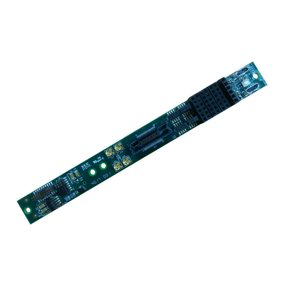
RS-232 connection through a standard USB cable, connectivity for 20-pin ARM Cortex Debug interface, 38-pin MICTOR and 28-pin PMOD interface with GPIO interface. Figure 1: Top and Bottom View of SOC_IO_HT3 daughter board © 2017 E-elements Tech. SOC_IO_HT3 Reference Manual November 2017... -
Page 7: Soc_Io_Ht3
1 20-pin ARM Cortex Debug + ETM Connector • 2 Micro-USB Ports • 2 pairs of Differential MMCX Clock Connectors (for Global Clocks) • 1 38-pin MICTOR Connector • 1 12-pin Pad for Other GPIO © 2017 E-elements Tech. SOC_IO_HT3 Reference Manual November 2017... -
Page 8: Layout
SOC_IO_HT3 Layout Layout Figure 2: Top and Bottom (dotted line) SOC_IO_HT3 Layout © 2017 E-elements Tech. SOC_IO_HT3 Reference Manual November 2017... -
Page 9: Block Diagram
Figure 3 show the connectivity between the SOC_IO_HT3 daughter board’s headers and connectors to the HT3 connector. The HT3 I/O pin mapping is described in the J1 pin table on page 15. Figure 3: SOC_IO_HT3 Block Diagram © 2017 E-elements Tech. SOC_IO_HT3 Reference Manual November 2017... -
Page 10: Daughter Board Placement
I/O standards can be used for the signal pins. The SOC_IO_HT3 card connected to HAPS-80 through HT3 connector, Figure 4 is the example of card installed Figure 4: SOCIO_HT3 mounted on HAPS-80 system © 2017 E-elements Tech. SOC_IO_HT3 Reference Manual November 2017... -
Page 11: Haps Gpio Headers
Pin 1-2: J28 Output pin 1 GPIO_A9 Pin 3-4: J28 Output pin 2 GPIO_A10 Pin 5-6: J28 Output pin 3 GPIO_A11 Pin 7-8: J28 Output pin 4 Table 1: SOCIO_HT3 Control Signals © 2017 E-elements Tech. SOC_IO_HT3 Reference Manual November 2017... -
Page 12: Mictor
J1 pin table on page 17. The ten I/Os allocated to this interface are routed to the ARM connector from GPIO Header J1 and are also available for alternate uses. © 2017 E-elements Tech. SOC_IO_HT3 Reference Manual November 2017... -
Page 13: Micro-Usb Port
USB device in the same way as it would access a standard COM port. Part: USB to serial UART Interface Number: FT234XD Web address: ftdichip.com Note: VCCO must be configured to 1.8V © 2017 E-elements Tech. SOC_IO_HT3 Reference Manual November 2017... -
Page 14: Clocks
Table 1 is a list of clock connections for each MMCX connector. MMCX Connector Direction Source J12/J13 Differential Output C0P/C0N J15/J17 Differential Output C1P/C1N Table 2: MMCX Clock Connections CLK_C0_P CLK_C0_N CLK_C1_P CLK_C1_N Figure 6: DIFF Clocks © 2017 E-elements Tech. SOC_IO_HT3 Reference Manual November 2017... -
Page 15: Pin Tables
SOC_IO_HT3 Pin Tables Pin Tables HT3 Connector © 2017 E-elements Tech. SOC_IO_HT3 Reference Manual November 2017... -
Page 16: Other Gpio Connector
GPIO_A3 GPIO_A3 GPIO_A7 GPIO_A7 VCCO VCCO GPIO_B0 GPIO_B0 GPIO_A8 GPIO_A8 GPIO_B1 GPIO_B1 GPIO_A9 GPIO_A9 GPIO_B2 GPIO_B2 GPIO_A10 GPIO_A10 GPIO_B3 GPIO_B3 GPIO_A11 GPIO_A11 VCCO GPIO_B4 GPIO_B4 GPIO_B5 GPIO_B5 GPIO_B6 GPIO_B6 GPIO_B7 GPIO_B7 © 2017 E-elements Tech. SOC_IO_HT3 Reference Manual November 2017... -
Page 17: Mictor Connector
GPIO_C9 GPIO_B9 GPIO_A2 GPIO_A6 GPIO_C10 GPIO_B10 GPIO_A3 GPIO_A7 GPIO_C11 GPIO_B11 3.3V 3.3V 3.3V 3.3V 3.3V 3.3V GPIO_A8 GPIO_B0 GPIO_B4 GPIO_A9 GPIO_B1 GPIO_B5 GPIO_A10 GPIO_B2 GPIO_B6 GPIO_A11 GPIO_B3 GPIO_B7 3.3V 3.3V 3.3V © 2017 E-elements Tech. SOC_IO_HT3 Reference Manual November 2017... -
Page 18: Arm Cortex Debug+Etm Connector
TRACEDATA_2 TRACEDATA_3 FT234XD UART/USB DATA_N GPIO_C0 DATA_N GPIO_C3 OUT_N VCCO OUT_N VCCO GPIO_C7 GPIO_C2 OUT_N GPIO_D0 OUT_N GPIO_C4 DATA_P DATA_P GPIO_C6 GPIO_C1 Micro USB Connector VCCO VCCO USBD_N USBD_N USBD_P USBD_P © 2017 E-elements Tech. SOC_IO_HT3 Reference Manual November 2017...
Need help?
Do you have a question about the SOC IO HT3 and is the answer not in the manual?
Questions and answers