Table of Contents
Advertisement
Quick Links
Advertisement
Table of Contents

Related Manuals for E-ELEMENTS SOC DBG HT3

Summary of Contents for E-ELEMENTS SOC DBG HT3
- Page 1 SOC_DBG_HT3 EH2012003030 Reference Manual January 2021 ver0.3...
- Page 2 Copyright Notice and Proprietary Information © 2020 E-elements Technology Co., Ltd. These all associated documentation are proprietary to E-elements and may only be used pursuant to the terms and conditions of a written license agreement with E-elements. All other use, reproduction, modification, or distribution of the associated documentation is strictly prohibited.
-
Page 3: Revision History
Revision History Date Comment Jun 2020 V0.1 Initial version. V0.2 Change the ping of nSRST and nTRST. Nov 2020 Jan 2021 V0.3 Add the Level shift in block diagram. © 2020 E-elements Tech. SOC_DBG_HT3 Reference anual January 2021... -
Page 4: Table Of Contents
ARM Debug interface....................12 Type-C USB Port ......................13 Pin Tables ........................14 HT3 Connector ...................... 14 ARM MIPI60 ......................15 ARM Cortex Debug+ETM Connector ..............16 Mictor Connector ....................16 Jumper …………………………………………………………………………………16 PMOD Connector....................17 © 2020 E-elements Tech. SOC_DBG_HT3 Reference anual January 2021... -
Page 5: Soc_Dbg_Ht3
® HapsTrak 3 Connector Considerations The HT3 connectors must be attached carefully! If connected improperly socket pins can be deformed or holding rail ends can become damaged. © 2020 E-elements Tech. SOC_DBG_HT3 Reference anual January 2021... -
Page 6: Overview
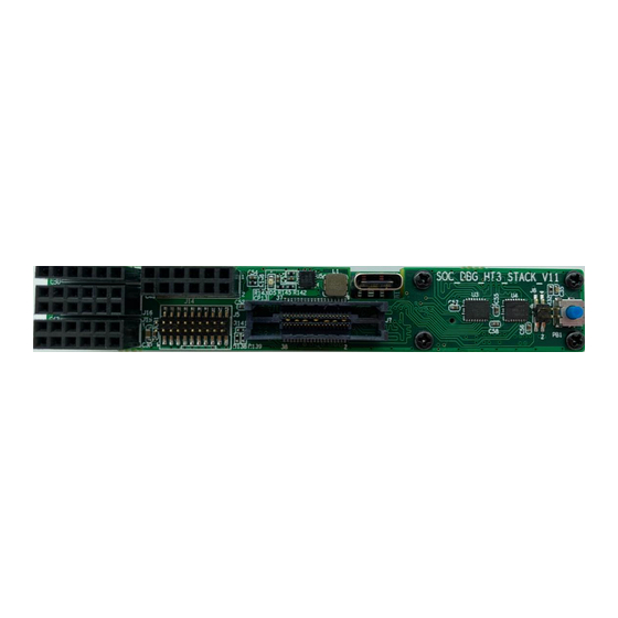
RS-232 connection through a standard USB cable, connectivity for 20-pin ARM Cortex Debug interface, 38-pin MICTOR and 28-pin PMOD interface with GPIO interface. Figure 1: Top View of SOC_DBG_HT3 daughter board © 2020 E-elements Tech. SOC_DBG_HT3 Reference Manual January 2021... -
Page 7: Soc_Dbg_Ht3
3 8-pin + 1 4-pin 3.3V-level GPIO Headers • 1 20-pin ARM Cortex Debug + ETM Connector • 1 Micro-USB Ports • 1 38-pin MICTOR Connector • 1 12-pin Pad for Other GPIO • 1 60-pin MIPI60 Connector © 2020 E-elements Tech. SOC_DBG_HT3 Reference Manual January 2021... -
Page 8: Layout
SOC_DBG_HT3 Layout Layout Figure 2: Top and Bottom(dotted line) of SOC_DBG_HT3 stacked board layout Figure 3: Top and Bottom(dotted line) of SOC_DBG_HT3 base board layout © 2020 E-elements Tech. SOC_DBG_HT3 Reference Manual January 2021... -
Page 9: Block Diagram
Figure 4 show the connectivity between the SOC_DBG_HT3 daughter board’s headers and connectors to the HT3 connector. The HT3 I/O pin mapping is described in the JX1 pin table on page 14. Figure 4: SOC_DBG_HT3 Block Diagram © 2020 E-elements Tech. SOC_DBG_HT3 Reference Manual January 2021... -
Page 10: Daughter Board Placement
I/O standards can be used for the signal pins. The SOC_DBG_HT3 card connected to HAPS-80 through HT3 connector, Figure 5 is the example of card installed. Figure 5: SOC_DBG_HT3 mounted on HAPS-80 system © 2020 E-elements Tech. SOC_DBG_HT3 Reference Manual January 2021... -
Page 11: Haps Gpio Headers
Jumpers provide different configuration options dependent on your requirements. Jumper Description Short: U13 UART(TX2/RX2 and TX3/RX3) output disable. Open: U13 UART(TX2/RX2 and TX3/RX3) output enable. Short 1-2: connect to PB1(low active). © 2020 E-elements Tech. SOC_DBG_HT3 Reference Manual January 2021... -
Page 12: Button
JX1 pin table on page 14. The ten I/Os allocated to this interface are routed to the ARM connector from GPIO Header JX1 and are also available for alternate uses. © 2020 E-elements Tech. SOC_DBG_HT3 Reference Manual January 2021... -
Page 13: Type-C Usb Port
USB device in the same way as it would access a standard COM port. Part: USB to serial UART Interface Number: FT4232HL Web address: ftdichip.com Note: VCCO must be configured to 1.8V © 2020 E-elements Tech. SOC_DBG_HT3 Reference Manual January 2021... -
Page 14: Pin Tables
SOC_DBG_HT3 Pin Tables Pin Tables HT3 Connector © 2020 E-elements Tech. SOC_DBG_HT3 Reference Manual January 2021... -
Page 15: Arm Mipi60
TRACE_D0 TRACE_D20 TRACE_D1 TRACE_D21 TRACE_D2 TRACE_D22 TRACE_D3 TRACE_D23 TRACE_D4 TRACE_D24 TRACE_D5 TRACE_D25 TRACE_D6 TRACE_D26 TRACE_D7 TRACE_D27 TRACE_D8 TRACE_D28 TRACE_D9 TRACE_D29 TRACE_D10 TRACE_D30 TRACE_D11 TRACE_D31 TRACE_D12 TRACE_D13 TRACE_D14 TRACE_D15 TRACE_D16 TRACE_D17 TRACE_D18 SOC_DBG_HT3 Reference Manual © 2020 E-elements Tech. January 2021... -
Page 16: Arm Cortex Debug+Etm Connector
VCCO RTCK VCCO TCK_ SWDCLK TRACE_D7 TMS_ SDWIO TRACE_D6 TDI_NC TRACE_D5 nTRST TRACE_D4 TRACE_D15 TRACE_D3 TRACE_D14 TRACE_D2 TRACE_D13 TRACE_D1 TRACE_D12 TRACE_D11 TRACE_D10 VCCO TRACE_D9 Trace_CTL TRACE_D8 TRACE_D0 Jumpers J8(Stacked board) nTRST SOC_DBG_HT3 Reference Manual © 2020 E-elements Tech. January 2021... -
Page 17: Pmod Connector
J15(Stacked board) PMOD_IO2[0] PMOD_IO2[1] PMOD_IO2[2] PMOD_IO2[3] PMOD_IO2[4] PMOD_IO2[5] PMOD_IO2[6] PMOD_IO2[7] 3.3V 3.3V J16(Stacked board) PMOD_IO3[0] PMOD_IO3[1] PMOD_IO3[2] PMOD_IO3[3] PMOD_IO3[4] PMOD_IO3[5] PMOD_IO3[6] PMOD_IO3[7] 3.3V 3.3V J17(Stacked board) PMOD_IO0[0] PMOD_IO0[1] PMOD_IO0[2] PMOD_IO0[3] 3.3V SOC_DBG_HT3 Reference Manual © 2020 E-elements Tech. January 2021...
Need help?
Do you have a question about the SOC DBG HT3 and is the answer not in the manual?
Questions and answers