Advertisement
Quick Links
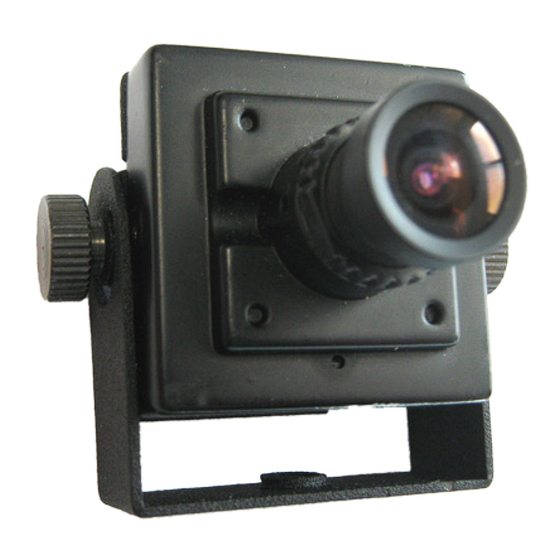
in30S2N1L30 Ver.3
4-in-1
ATM Camera
Quick Start Guide
Before operating this product, please read this quick-start guide to ensure proper use.
Please store these instructions a safe place for future reference.
FEATURES
•
Compact Design
•
HLC, BLC, DEFOG
•
Fixed lens
•
Sens Up
•
1080P Full HD High Sensitivity Sensor
•
On Screen Menu
•
800TVL Resolution in analog mode
•
12VDC or 24VAC when using power
•
Selectable , Analog, TVI, CVI, AHD
module
•
Wide Dynamic Range
PRECAUTIONS
1. Before installing and operating the unit, please read this manual carefully.
2. Precision components are contained in this camera, please avoid violent vibrations during
installation and maintenance. Do not connect the power until you have completed the
installation.
3. Please obey all local electrical wiring regulations when using this unit.
4. Do not use abrasive or corrosive materials for cleaning. Use only a soft cloth for cleaning.
5. To prevent damage to the lens or sensor, do not point the camera directly into the sun
or very strong light sources.
6. Do not use the camera outside it's working temperature (-10°C~ 50°C / 14°F ~122°F) or
humidity (<90%) ranges.
7. Ensure that the power supply meets the current requirements of the camera and that
the supply voltage is inside the tolerances of the camera: 24VAC ±10%
8. Ensure that the fixings used are adequate to support the load of camera.
9. In case of camera failure, do not attempt to dismantle or service the camera yourself.
Please refer to qualified service personnel for repair of the camera.
CONNECTIONS
Connections for video and power are as follows
1. Remove cover from module. ③
2. Mount power module utilizing the two holes in base plate. ①
3. Attach incoming power cable under the screw terminals ⑤ on the power module and
tighten down.
4. Verify 3 pin molex ⑥ is plugged into power board. ④
5. After mounting the ATM camera, plug the 10 pin Molex ⑧ into the back of the
ATM camera.
6. Connect BNC cable. ⑦
7. Power up unit and test.
Note: Be sure to protect your BNC connector so it will
not ground out on ATM machine.
Secure all cable approprialty inside ATM
MOUNTING POWER MODULE AND ATM BRACKETS
⑧
①
②
The camera comes with a number of bracket options, to enable the camera to be mounted
and positioned in restricted spaces. The brackets can be assembled in different combinations,
with different pivot positions, to allow versatile installation.
The kits of parts includes:
1x Short U-Bracket
4x M2 Knurled lock screws
①
1x Long U-Bracket
pivot screws
②
1x Extension Bracket
4x M2 Domed lock screws
③
①
④
⑥
⑤
:
①
③
③
④
⑤
④
⑤
The different bracket configurations are shown above:
Depending on the available installation space, the knurled lock screws
with the spare domed lock screws
Do not overtighten the lock screws. Remember to secure
. ⑥
the power/video lead to the bracket.
OSD ACCESS
The camera is supplied in a general configuration that will suit the majority of installation
requirements. Should advanced configuration be required then the optional iCCTV™ compliant
UTC (up the coax) Programmer may connected to provide access to the camera. The UTC
programmer may be used remotely from the camera (e.g. at a DVR), such that direct access to
the camera is not required for its use
To view the On Screen Display, connect the Video-In connector of a UTC controller to the
Video-Out connector of the camera. Connect the Video-Out of the UTC controller to a display
monitor, as shown below.
To activate the camera OSD, depress the joystick button on
the Controller for 1 second (Correct operation of the UTC
controller: operation is confirmed when LED is latched on.)
Push the joystick to select a menu from the list.
Push the joystick to change the selected value.
Press the joystick button to call the sub-menu or execute a
command.
To return from a sub-menu to the previous menu, select
"Previous Page" and press the joystick button.
⑦
,
When the OSD menu is launched, you are presented with the adjacent opening
screen.
⑥
A menu option followed by a indicates the presence of a sub-menu. Options
⑤
set to OFF will not show a until set to ON
④
Use RETURN to return to the previous menu.
③
4x M2 Flat
④
⑤
⑥
②
④
Exposure menu:
•
Lens- Manual
•
BRIGHTNESS - sets the level of the overall brightness
•
SHUTTER- OFF, 1/60~1/120K. (1/50~120K PAL) Set this on to reduce the
exposure time of each image. This can be used to reduce blur in images
⑤
with fast changing content.
•
FLK- Use this when flicker is observed in the image under fluorescent
lighting. When FLK is ON, the shutter menu is disabled.
②
•
SENS UP - Slows frame rate and increases low light sensitivity
•
AGC- Off or Level Control -Used to adjust overall AGC level
⑤
④
④
⑤
may be interchanged
④
MAIN MENU
Presets..
Basic Functions..
Image Functions..
SAVE/EXIT..
OSD MAIN MENU
MENU
EXPOSURE
BACKLIGHT
WDR
DAY/NIGHT
WHITE BALANCE
DNR
Middle
IMAGE
MOTION
OFF
SYSTEM
EXIT
SAVE
EXPOSURE MENU
IMAGE
LENS
MANUAL
BRIGHTNESS 10
SHUTTER
AUTO
SENS-UP
x4
AGC
10
RETURN
Advertisement

Related Manuals for Remote Alert in30S2N1L30

Summary of Contents for Remote Alert in30S2N1L30
- Page 1 MOUNTING POWER MODULE AND ATM BRACKETS OSD MAIN MENU ⑧ ⑦ When the OSD menu is launched, you are presented with the adjacent opening in30S2N1L30 Ver.3 screen. ⑥ A menu option followed by a indicates the presence of a sub-menu. Options 4-in-1 ⑤...
- Page 2 ANALOG MODE: HD-T (TVI), HD-C (CVI), Humidity Less than 90%, non condensing HD-A (AHD), CVBS Order Codes Lens in30S2N1L30 Ver.3 OUTPUT • CONFIRM-If you change any selection in COLOR BAR the output mode press and hold the enter...
Need help?
Do you have a question about the in30S2N1L30 and is the answer not in the manual?
Questions and answers