
Related Manuals for ABB 62831 U-WL-500


Summary of Contents for ABB 62831 U-WL-500
- Page 1 Product manual │ 05.11.2024 62831 U-WL-500 Blind actuator, FM, WL Bra n d i n g -- R e l e a s e 2 0 1 8 - 0 1 - 0 1...
-
Page 2: Table Of Contents
Dismantling ........................... 22 Overview of applications........................... 23 Expansion stage "Device control" ....................24 Expansion stage "Room control" ....................25 Expansion stage "Home automation" .................... 26 Overview ABB-free@home ® Next App areas ................27 Overview of start screen........................ 28 System integration ........................29 System requirements ........................ - Page 3 Table of contents Commissioning in the expansion stage "Device control" ............... 33 Commissioning of the expansion stage "Room control" ..............36 Commissioning of the expansion stage "Home automation" ............39 9.5.1 Authorizations ............................ 39 9.5.2 Coupling of wireless devices with the System Access Point ............39 9.5.3 Add device ............................
-
Page 4: Notes On The Instruction Manual
If you pass the device on, also include this manual along with it. ABB accepts no liability for any failure to observe the instructions in this manual. If you require additional information or have questions about the device, please contact ABB or visit our Internet site at: https://new.abb.com/en... -
Page 5: Safety
However, residual hazards remain. Read and adhere to the safety instructions to prevent hazards of this kind. ABB accepts no liability for any failure to observe the safety instructions. Information and symbols used The following Instructions point to particular hazards involved in the use of the device or provide... -
Page 6: Intended Use
Each use not listed in Chapter 3.2 “Intended use“ on page 6 is deemed improper use and can lead to personal injury and damage to property. ABB is not liable for damages caused by use deemed contrary to the intended use of the device. The associated risk is borne exclusively by the user/operator. -
Page 7: Target Group / Qualifications Of Personnel
Safety Target group / Qualifications of personnel 3.4.1 Operation No special qualifications are needed to operate the device. 3.4.2 Installation, commissioning and maintenance Installation, commissioning and maintenance of the device must only be carried out by trained and properly qualified electrical installers. The electrical installer must have read and understood the manual and follow the instructions provided. -
Page 8: Cyber Security
Cyber security The industry faces intensifying cyber security risks. In order to increase stability, safety and robustness of its solutions, ABB has formally established cyber security robustness testing as part of the product development process. The following measures are prerequisite for the safe operation of your ABB-free@home ®... - Page 9 Safety Personal data (also telemetry data) Personal data consists of details regarding the personal or factual circumstances of a certain or identifiable natural person. Information that cannot be connected directly or indirectly to your identity, such as the number of users of a page, is not personal data. In the case MyBuildings these consist of data you have made available to us yourself, such as registration data, contact data, or data added in connection with the services used, such as bank data, as well as data of devices which have been allocated to the user account.
- Page 10 Safety Notice on privacy policies: https://new.abb.com/privacy-policy/en Concrete handling of personal data that are obtained, stored and processed by the ABB- free@home ® System Access Point 2.0: Revocation of Description Processing options Obtaining consent consent The name of the user is...
- Page 11 Safety Concrete handling of telemetry data that are recorded, stored and processed by ABB- free@home ® System Access Point 2.0: The telemetry data include all sensors and actuators that are connected via the cable-bound or wireless interfaces with the SysAP. Also IP-connected devices that are controlled by the SysAP or from which it requests information, are enclosed (e.g.
-
Page 12: Secure Shell Protocol
This function can only be used by the ABB technician, not by the end customer. The end customer always has his device under his own control. Without activation by the user/end customer, the interface cannot be used by anyone. - Page 13 General deleting functions Notice Further instructions are available in the corresponding chapter of this product manual or in the system manual for ABB-free@home ® Shut-down, archiving and destruction If the device is to be taken out of operation, archived or destroyed, first remove al sensitive and personal data from the device with the function “Reset to factory settings”...
-
Page 14: Safety Instructions
Safety Safety instructions Danger - Electric voltage! Electric voltage! Risk of death and fire due to electric voltage of 100 … 240 V. Dangerous currents flow through the body when coming into direct or indirect contact with live components. This can result in electric shock, burns or even death. -
Page 15: Information On Protection Of The Environment
Information on protection of the environment Information on protection of the environment Environment Consider the protection of the environment! Used electric and electronic devices must not be disposed of with domestic waste. – The device contains valuable raw materials which can be recycled. Therefore, dispose of the device at the appropriate collecting depot. -
Page 16: Setup And Function
Setup and function Setup and function Functions The device serves for the remote control of blind motors. It can be operated as ABB wireless device. Also the integration into a ABB-free@home wireless system is flexTronics ® ® possible. The device can be combined with other participants of the ABB-free@home ®... -
Page 17: Technical Data
Technical data Technical data Technical data Description Value – free@home flex Transmission protocol – Bluetooth Transmission frequency 2.4 - 2.48 GHz WL (wireless) < 15 dBm Maximum transmission power Bluetooth LE (BLE) < 10 dBm Standby power consumption 0.3 W Connection 230 V AC ±10%, 50/60 Hz Maximum load... -
Page 18: Connection And Installation
(e.g. computers, audio and video systems) should be at least 1 m. Note Planning and application instructions for the system are available in system manual for ABB-free@home ® . This can be downloaded via www.abb.com/freeathome. Product manual 2CKA000073B0086... -
Page 19: Safety Instructions
Connection and installation Safety instructions Danger - Electric shock due to short-circuit! Risk of death due to electrical voltage of 100 to 240 V during short-circuit in the low-voltage line. – Low-voltage and 100 - 240 V lines must not be installed together in a flush- mounted box! –... -
Page 20: Circuit Diagrams
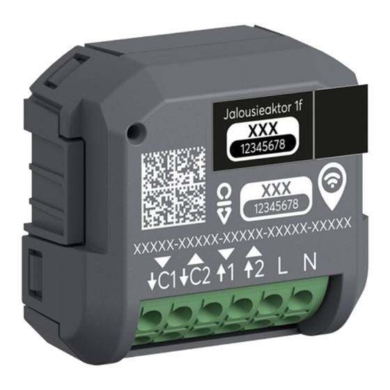
↑2 Motor output 2 = “Up” ↓C1 Extension unit input 1 “Down” ↓C2 Extension unit input 2 = “Up” Fig. 6: Electrical connection 62831 U-WL-500 with extension unit Notice For the connection of two motors a cut-off relay must be installed! Product manual 2CKA000073B0086... -
Page 21: Requirements For The Electrician
Connection and installation Requirements for the electrician Danger - Electric voltage! Install the device only if you have the necessary electrical engineering knowledge and experience. Incorrect installation endangers your life and that of the user of the electrical ■ system. Incorrect installation can cause serious damage to property, e.g. -
Page 22: Mounting
Connection and installation Mounting Notice The device can be mounted in a ceiling box or flush-mounted box such as behind a socket outlet or a switch. Check beforehand whether there is sufficient space. To install the device, perform the following steps: 1. -
Page 23: Overview Of Applications
For more detailed information, see chapter “Expansion stage "Room control"“ on page 25. Home automation ■ – In this expansion stage the remote control is made with the ABB-free@home ® Next App. The parameter setting is made in the web-based interface of the System Access Point of a ABB-free@home ®... -
Page 24: Expansion Stage "Device Control
The access from the smartphone to the networked device is carried out with Bluetooth via ■ the ABB-free@home Next App. ® The remote control and parameter setting is carried out via the ABB-free@home ® Next App. ■ Fig. 8: Device control expansion stage (individual control) Product manual 2CKA000073B0086 │24... -
Page 25: Expansion Stage "Room Control
Overview of applications Expansion stage "Room control" In this expansion stage the configuration, remote control and parameter setting of a blind actuator and additional devices are made with the ABB-free@home ® Next App. Up to 32 devices can be linked with each other in the expansion stage via a mesh network. -
Page 26: Expansion Stage "Home Automation
Expansion stage "Home automation" In this expansion stage the remote control is made with the ABB-free@home Next App. The ® parameter setting is made in the web-based interface of the System Access Point of a ABB- free@home ® -configuration. This expansion stage is totally networkable with the entire range of functions of a ABB- free@home configuration, such as voice control, logic functions, external access, etc.. -
Page 27: Overview Abb-Free@Home ® Next App Areas
Overview of applications Overview ABB-free@home Next App areas ® In the following you see an example of the function and operating areas of the app for the device. Overview area Parameters General settings (Example) (Example) Others (example) Change of device name and the... -
Page 28: Overview Of Start Screen
(see the detailed view in the illustration [B1]). Hamburger menu Tapping on the Hamburger menu opens the function overview of the ABB- free@home ® Next App (see the detailed view in the illustration [C1]). -
Page 29: System Integration
Detail view of function "Lock at position. [B1] Detailed view of the drop-down menu for adding an additional device. [C1] Detailed view of the function overview of the ABB-free@home ® Next App. Table. 6: Overview of start screen - detailed view... -
Page 30: System Requirements
ABB-free@home ® Next App app . In the following the designation "Smartphone" is used representatively. Prerequisites: The current version of the app ABB-free@home ® Next App is installed on your smartphone, ■ at least however, version 2.4 The smartphone has a Bluetooth function. -
Page 31: System Requirements: "Room Control
The current version of the app ABB-free@home ® Next App is installed on your smartphone, ■ at least however, version 2.4. The device is in the radio range of the System Access Point or an additional ABB- ■ free@home ® wireless device. -
Page 32: Commissioning
A device that has already been logged in must be reset to enable it to be set again into programming mode. – The device can be reset via the ABB-free@home ® Next App app.(see chapter “Settings / maintenance“ on page 63/ Chapter 10.8 “Factory settings“... -
Page 33: Identifying The Device
Commissioning Identifying the device Before commissioning, the device can be identified in the ABB-free@home Next App for 30 ® minutes after a voltage reset. This function is especially helpful when several device are made operational at the same time. Tor identify a device, proceed as follows: 1. - Page 34 Commissioning Fig. 12: Integrating the device [D] - [F] (example illustration) 5. Select “New installation” when there is none yet [D]. – Select the desired installation type and confirm with "Continue" [E]. – Assign a name for the new installation and select "Continue". –...
- Page 35 7. The app indicates that the device was added successfully to the installation [H]. Complete the process via "Finished" or, if necessary, repeat the steps via the option "Add an additional device". The device is connected with the app ABB-free@home ® Next App and can be configured via the parameters (see chapter “Overview of parameters“...
-
Page 36: Commissioning Of The Expansion Stage "Room Control
1. Activate the Bluetooth on your smartphone and connect the device to the power supply. Fig. 14: Integrating the device [A] - [C] (example illustration) 2. Open the app ABB-free@home ® Next App and tap on the plus icon [A]. - Page 37 Commissioning Fig. 15: Integrating the device [D] - [F] (example illustration) 5. Select “New installation” when there is none yet [D]. – Select the desired installation type and confirm with "Continue" [E]. – Register yourself at MyBuildings [F]. – Assign a name for the new installation and select "Continue". –...
- Page 38 7. The app indicates that the device was added successfully to the installation [I]. Complete the process via "Finished" or, if necessary, repeat the steps via the option "Add an additional device". The device is connected with the app ABB-free@home ® Next App and can be configured via the parameters (see chapter “Overview of parameters“...
-
Page 39: Commissioning Of The Expansion Stage "Home Automation
Authorizations To be able to make settings on the system during commissioning, the login of the fitter is necessary. Notice Detailed information on user management is available in the ABB-free@home ® system manual. Notice The setting options and illustrations described in this chapter assume a login as fitter in the web-based user interface of the System Access Point. - Page 40 – Close the notification window "Search for wireless devices" by clicking on "OK". – The System Access Point consecutively scans all ABB-free@home ® wireless devices. Devices that are in programming mode are automatically integrated into the system. The search process in the System Access Point ends 10 minutes after the last device has been found.
-
Page 41: Add Device
Commissioning 9.5.3 Add device Fig. 19: Devices, scenes and groups 1. Select "Devices, scenes & groups" via the main menu or the page menu in the user interface of the System Access Point. – The "Building plan" opens. Fig. 20: Opening the building plan and list of components (example illustration) 2. - Page 42 Commissioning Fig. 21: Pulling the device out of the menu bar (example illustration) 4. Select the desired device and pull it into the building plan via drag-and-drop. – If you pull a new device into a room via drag-and-drop, a pop-up window opens in which all devices that are located in the system are listed and which have not been allocated to a room.
- Page 43 Commissioning The device can be identified via the serial number or via switching. Fig. 23: Allocation of devices A window opens which lists all the devices suitable for the application selected. Identification via serial number Fig. 24: Identification via serial number 6.
- Page 44 Commissioning Identification via switching If several devices are listed in the device list, you can identify them by switching the actual device. Fig. 25: Identification via switching (example illustration) 1. Open the device list. 2. Press the "Identification" button [1] and then switch the actual device. Or, as alternative, press only the button [2] in the web interface.
-
Page 45: Commissioning By Scanning The Qr Code
4. Use the camera of your smartphone to scan the printed QR code on the rear side of the device. Notice To be able to scan the QR code via the app ABB-free@home ® Next App , you must allow access to the camera when you are requested. - Page 46 Commissioning Fig. 28: Integrating the device [D] - [F] (example illustration) 5. Select “New installation” when there is none yet [D]. – Select the desired installation type and confirm with "Continue" [E]. – Assign a name for the new installation and select "Continue". –...
- Page 47 Commissioning Fig. 29: Integrating the device [G] - [H] (example illustration) 7. The app indicates that the device was added successfully to the installation [H]. Complete the process via "Finished" or, if necessary, repeat the steps via the option "Add an additional device".
-
Page 48: Operation
Operation Operation 10.1 Display elements Fig. 30: Display elements [A] LED Status LED Status Description 5 flashes The device flashes five times because the function “Identify” was activated. Flashing The device is in programming mode. Table. 7: Conditions of status LED Product manual 2CKA000073B0086 │48... -
Page 49: Overview Of Parameters
Operation 10.2 Overview of parameters For the configuration of the parameters, select the installation and the desired device. Then scroll down to the parameters. The overview shows the individual parameters in their sequence of appearance during operation. Notice Some changes must, if necessary, be saved via the "Save" button for them to become effective. -
Page 50: Overview Of Actuator Parameters
Operation 10.2.1 Overview of actuator parameters Channel name Here an individual name can be assigned to the channel. Function The function of the actuator is selected already during the calibration of the device. However, it can be changed later if necessary. Blind actuator For controlling of motorized blinds. - Page 51 Operation Total time of upward movement [s] Setting the movement time of the curtain to the top end position via the sliding controller or by entry in the text field. 3 ... 600 s Step size: 1 s Motor pause time [ms] The time in which the motor does not move after activation can be set via the sliding controller or input in the text field.
- Page 52 Operation Parameters of function “Roller blind actuator” / “Roof window actuator” / “Awning actuator” Operating mode The curtain moves continuously up/down at a long press of the button and remains in the top/bottom position. The movement of the curtain can be stopped with a brief press of a button.
- Page 53 Operation Behaviour at cancelling of alarms Here the behaviour of the curtain can be selected when the alarm message of the alarm transmitter is no longer pending. The curtain remains in the position that was taken when the alarm was Remain on the position triggered.
-
Page 54: Overview Of Sensor Parameters
Operation 10.2.2 Overview of sensor parameters Notice The device is a an actuator. On the extension unit input a conventional button can be wired and configured here. Also the connection of a Sub-insert flex is possible. Channel name Here an individual name can be assigned to the channel. Block local operation With this function the operation can be deactivated via the button. - Page 55 Operation Parameters of function “Roller blind operation” Operating mode The curtain moves continuously up/down at a long press of the button and remains in the top/bottom position. The movement of the curtain can be stopped with a brief press of a button. Moving with a long press At a brief press of the button the curtain moves one step up/ down or turns the slats by one position.
-
Page 56: Individual Operating Functions
Operation 10.3 Individual operating functions Calibration Blind actuators are used for numerous applications. They can, for example, control a motorized roof window or an awning. The device can be optimized for one of these applications via the function “Calibration”. The necessary values such as the total "Up", "Down" movement times, the adjustment times of the slats and the time of the motor are determined with the calibration. - Page 57 Operation Links Sensors and actuators can be linked with each other. This allows simple On/Off circuits or two- way circuits to be implemented. Under the "Links", you can create, delete or edit links. In addition, you can see for which devices a link has been created.
- Page 58 Icon "Arrow up" on rocker The behaviour at cancelling of alarms is specified per channel in the parameter settings of the actuator and is valid for all alarm types. When using a ABB-free@home ® window contact, additional subsequent events occur.
-
Page 59: Automation/Timer
Operation 10.4 Automation/Timer Notice The device is not equipped with batteries. – Time programs are stopped at a power failure. – The time in the device is synchronized again only at the next connection with the app. Up to 28 switching times can be programmed via the automation. Each timer has a weekday function and can be programmed for one or several weekdays. -
Page 60: Automation/Timer Settings
Operation 10.4.1 Automation/Timer settings Different switching times can be programmed in the automation area. The following overview shows the setting options and parameters in their sequence of appearance during operation. Notice Performed changes must, if necessary, be saved via the "Save" button for them to become effective. - Page 61 Operation Repetition on every Mon/Tue/Wed/Thu/Fri/Sat/Sun Specifying the weekdays at which the timer is to repeat itself. The standard setting. The timer switches on all weekdays at Switching on all weekdays the same time. Live mode If the live-mode is activated, at the change of the configuration the actuator changes into the timer settings to display the configured switching state.
-
Page 62: General Settings
Operation 10.5 General settings The name of the device can be changed in the "General settings" and the position (floor/room) inside the house can be defined. General settings General settings Expansion stage Room control and Home Expansion stage Device control automation Table. -
Page 63: Settings / Maintenance
Operation 10.6 Settings / maintenance Settings / maintenance Settings / maintenance Expansion stage Room control and Home Expansion stage Device control automation Information about the device Parameters [1] Overview of the device data [1] Channel selection Maintenance Information about the device [2] Setting and changing device password [2] Overview of the device data [3] Rebooting the device... -
Page 64: Firmware Update
Factory settings The device can be reset via the "Reset device” function (see chapter “Settings / maintenance“ on page 63). When the installation, with which the device is linked, is no longer available in the ABB- free@home ® Next App, the device can only be reset by a master reset. -
Page 65: Maintenance
Access to the device must be guaranteed for operation, testing, inspection, maintenance and repairs (according to DIN VDE 0100-520). Declaration of conformity ABB herewith declares, that radio system type 62831 U-WL-500 conforms to directive 2014/53/EU. The complete text of the EU Declaration of Conformity is available at the following Internet... -
Page 66: Index
Index Index Information and symbols used ......... 5 Information on protection of the environment ..15 Add device............41 Intended use ............6 Assigning a name ..........44 Authorizations ............. 39 Automation/Timer .......... 28, 59 Maintenance ............65 Automation/Timer settings ........60 Mounting ............ - Page 67 Index Product manual 2CKA000073B0086 │67...
- Page 68 Busch-Jaeger Elektro GmbH A member of the ABB Group Freisenbergstraße 2 D-58513 Lüdenscheid, Germany https://new.abb.com/en Customer service: Tel.: +49 2351 956-1600 © Copyright 2024 Busch-Jaeger Elektro GmbH All rights reserved...
Need help?
Do you have a question about the 62831 U-WL-500 and is the answer not in the manual?
Questions and answers