Table of Contents
Advertisement
Quick Links
INDOOR UNIT
SERVICE MANUAL
Models
MSZ-FT25VG
MSZ-FT35VG
MSZ-FT50VG
MSZ-FT25VGK
MSZ-FT35VGK
MSZ-FT50VGK
-
E1
-
E1
-
E1
-
E1
E2
ET1
SC1
,
,
,
-
E1
E2
ET1
SC1
,
,
,
-
E1
E2
ET1
SC1
,
,
,
CONTENTS
1. TECHNICAL CHANGES ······························2
2. PART NAMES AND FUNCTIONS ··················3
3. SPECIFICATION ········································4
4. NOISE CRITERIA CURVES ··························5
5. OUTLINES AND DIMENSIONS ·····················6
6. WIRING DIAGRAM ·····································7
7. REFRIGERANT SYSTEM DIAGRAM ··········· 11
8. SERVICE FUNCTIONS ······························ 12
9. MICROPROCESSOR CONTROL ················ 14
10. TROUBLESHOOTING ······························· 23
11. DISASSEMBLY INSTRUCTIONS ················· 38
PARTS CATALOG (OBB864)
Revision B:
• MSZ-FT25/35/50VGK -
added.
OBH864 REVISED EDITION-A is void.
No. OBH864
REVISED EDITION-B
SC2
,
SC2
,
SC2
,
Outdoor unit service manual
MUZ-FT∙VG Series (OBH865)
,
have been
E2
SC2
Advertisement
Table of Contents
Troubleshooting

Subscribe to Our Youtube Channel
Related Manuals for Mitsubishi Electric MSZ-FT25VG- E1


Summary of Contents for Mitsubishi Electric MSZ-FT25VG- E1
-
Page 1: Table Of Contents
Revision B: • MSZ-FT25/35/50VGK - have been added. OBH864 REVISED EDITION-A is void. INDOOR UNIT No. OBH864 REVISED EDITION-B SERVICE MANUAL Models MSZ-FT25VG MSZ-FT35VG MSZ-FT50VG MSZ-FT25VGK MSZ-FT35VGK MSZ-FT50VGK Outdoor unit service manual MUZ-FT∙VG Series (OBH865) CONTENTS 1. TECHNICAL CHANGES ······························2 2. -
Page 2: Technical Changes
Use the specified refrigerant only Never use any refrigerant other than that specified. Doing so may cause a burst, an explosion, or fire when the unit is being used, serviced, or disposed of. Correct refrigerant is specified in the manuals and on the spec labels provided with our products. We will not be held responsible for mechanical failure, system malfunction, unit breakdown or accidents caused by failure to follow the instructions. -
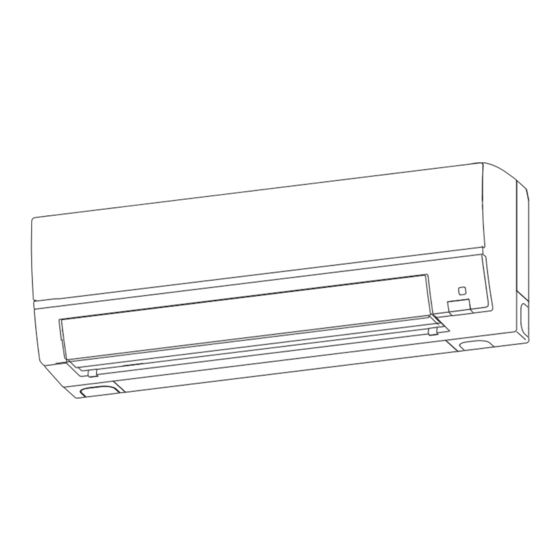
Page 3: Part Names And Functions
PART NAMES AND FUNCTIONS MSZ-FT25VG MSZ-FT35VG MSZ-FT50VG MSZ-FT25VGK MSZ-FT35VGK MSZ-FT50VGK Air inlet Front panel Wi-Fi interface Air fi lter (Air purifying fi lter) Air cleaning fi lter MSZ-FT•VG - MSZ-FT•VGK - E1 , ET1 , SC1 (Silver-ionized Horizontal vane air purifi er fi lter) Emergency operation switch Fan guard MSZ-FT•VGK -... -
Page 4: Specification
SPECIFICATION MSZ-FT25VG MSZ-FT35VG MSZ-FT50VG = model MSZ-FT25VGK MSZ-FT35VGK MSZ-FT50VGK Single phase 230 V, 50 Hz Power supply Cooling Power input Heating Cooling 0.26 0.29 0.33 Running 0.35 current *1 Heating 0.36 0.41 Model RC0J30-CV Cooling 0.26 0.29 0.33 Current *1 0.35 Heating 0.36... -
Page 5: Noise Criteria Curves
NOISE CRITERIA CURVES MSZ-FT25VG MSZ-FT35VG MSZ-FT25VGK MSZ-FT35VGK FUNCTION SPL(dB(A)) FUNCTION SPL(dB(A)) LINE LINE COOLING COOLING HEATING HEATING NC-70 NC-70 NC-60 NC-60 NC-50 NC-50 NC-40 NC-40 NC-30 NC-30 NC-20 NC-20 1000 2000 4000 8000 1000 2000 4000 8000 BAND CENTER FREQUENCIES, Hz BAND CENTER FREQUENCIES, Hz MSZ-FT50VG MSZ-FT50VGK... -
Page 6: Outlines And Dimensions
OUTLINES AND DIMENSIONS MSZ-FT25VG MSZ-FT35VG MSZ-FT50VG Unit: mm MSZ-FT25VGK MSZ-FT35VGK MSZ-FT50VGK OBH864B... -
Page 7: Wiring Diagram
WIRING DIAGRAM MSZ-FT25VG- MSZ-FT35VG- MSZ-FT50VG- OBH864B... - Page 8 MSZ-FT25VGK- MSZ-FT35VGK- MSZ-FT50VGK- OBH864B...
- Page 9 MSZ-FT25VGK- MSZ-FT35VGK- MSZ-FT50VGK- OBH864B...
- Page 10 MSZ-FT25VGK- PARÇA ADI SİGORTA (T3.15AL250V) FAN MOTORU KANAT MOTORU (YATAY ÜST) DIŞ KANAT MOTORU (YATAY ALT) ÜNİTEYE KANAT MOTORU İÇ ÜNİTE (DİKEY) ELEKTRONİK İÇ ÜNİTE VARİSTÖR KONTROL KARTI TERMİNAL KARTI RESİSTÖR ODA SICAKLIK TERMİSTÖRÜ BORU SICAKLIK SİVİÇ/BUZZER TERMİSTÖRÜ(ANA) KARTI BORU SICAKLIK TERMİSTÖRÜ(YARDIMCI) NOTLAR : 1.
-
Page 11: Refrigerant System Diagram
REFRIGERANT SYSTEM DIAGRAM MSZ-FT25VG MSZ-FT35VG MSZ-FT50VG Unit: mm MSZ-FT25VGK MSZ-FT35VGK MSZ-FT50VGK Refrigerant pipe ø9.52 (with heat insulator) Indoor coil Indoor thermistor heat RT12 exchanger Flared connection Indoor coil thermistor RT13 Room temperature thermistor RT11 Flared connection Refrigerant pipe ø6.35 (with heat insulator) Refrigerant flow in cooling Refrigerant flow in heating OBH864B... -
Page 12: Service Functions
SERVICE FUNCTIONS MSZ-FT25VG MSZ-FT35VG MSZ-FT50VG MSZ-FT25VGK MSZ-FT35VGK MSZ-FT50VGK 8-1. TIMER SHORT MODE For service, the following set time can be shortened by bridging the timer short mode point on the electronic control P.C. board. (Refer to 10-7.) • The set time for the ON/OFF timer can be reduced to 1 second for each minute. •... - Page 13 Third party Wi-Fi interfaces cannot be connected to MELCloud. MODE switch It selects modes. Mitsubishi Electric is not responsible for any (i) under performance of a sys- tem or any product; (ii) system or product fault; or (iii) loss or damage to any RESET switch It resets the system and ALL settings.
-
Page 14: Microprocessor Control
MICROPROCESSOR CONTROL MSZ-FT25VG MSZ-FT35VG MSZ-FT50VG MSZ-FT25VGK MSZ-FT35VGK MSZ-FT50VGK WIRELESS REMOTE CONTROLLER MSZ-FT25VG MSZ-FT25VGK MSZ-FT25VGK MSZ-FT35VG MSZ-FT35VGK MSZ-FT35VGK MSZ-FT50VG MSZ-FT50VGK MSZ-FT50VGK Signal transmitting section Distance of signal : About 6 m Beep(s) is (are) heard from the indoor unit when the signal is received. - Page 15 INDOOR UNIT DISPLAY SECTION Operation Indicator lamp The operation indicator at the right side of the indoor unit indicates the operation state. •The following indication applies regardless of shape of the indication. Indication Operation state Room temperature The unit is operating to About 2°C or more away reach the set temperature from set temperature...
-
Page 16: Operation Indicator
1. Cold air prevention control When the compressor is not operating or is starting, and the temperature of indoor heat exchanger and/or the room tem- perature is low or when defrosting is being done, the indoor fan will stop or rotate in Very Low speed. 2. -
Page 17: Auto Vane Operation
9-6. AUTO VANE OPERATION 1. Horizontal vane (1) Vane motor drive These models are equipped with a stepping motor for the horizontal vane. The rotating direction, speed, and angle of the motor are controlled by pulse signals (approximately 12 V) transmitted from indoor microprocessor. (2) The horizontal vane angle and mode change as follows by pressing VANE control button. -
Page 18: Timer Operation
2. Vertical vane (1) Vane motor drive These models are equipped with a stepping motor for the vertical vane. The rotating direction, speed, and angle of the motor are controlled by pulse signals (approximately 12 V) transmitted from microprocessor. (2) The vertical vane angle and mode change as follows by pressing WIDE VANE button. (3) Positioning (SWING) To confirm the standard position, the vane moves until it touches the vane stopper. -
Page 19: Program Timer
PROGRAM TIMER • OFF timer and ON timer can be used in combination. The set time that is reached first will operate first. • “ ” and “ ” display shows the order of OFF timer and ON timer operation. (Example 1) The current time is 8:00 PM. - Page 20 (3) Press , and buttons to set ON/OFF, time, and temperature. E.g. : [ON], [6:00] and [24°C] are selected. Pressing selects ON/OFF timer. Pressing Pressing adjusts the time. adjusts the tem- Pressing perature. deletes timer setting. * Hold down the button to change the time quickly. * The temperature can be set between 16°C and 31°C at COOL operation.
-
Page 21: I-Save Operation
9-9. NIGHT MODE ( ) OPERATION NIGHT MODE changes the brightness of the operation indicator, disables the beep sound and limits the noise level of the outdoor unit. (1) Press NIGHT MODE button during operation to activate NIGHT mode ( ). •... -
Page 22: Emergency/Test Operation
9-12. EMERGENCY/TEST OPERATION In the case of test run operation or the emergency operation, use the emergency operation switch in the right side of the indoor unit. The emergency operation is available when the remote controller is missing or has failed, or when the batteries in the remote controller are running down. -
Page 23: Troubleshooting
TROUBLESHOOTING MSZ-FT25VG MSZ-FT35VG MSZ-FT50VG MSZ-FT25VGK MSZ-FT35VGK MSZ-FT50VGK 10-1. CAUTIONS ON TROUBLESHOOTING 1. Before troubleshooting, check the following 1) Check the power supply voltage. 2) Check the indoor/outdoor connecting wire for miswiring. 2. Take care of the following during servicing 1) Before servicing the air conditioner, be sure to turn OFF the main unit first with the remote controller, and after confirm- ing the horizontal vane is closed, turn OFF the breaker and/or disconnect the power plug. - Page 24 10-2. FAILURE MODE RECALL FUNCTION Outline of the function This air conditioner can memorize the abnormal condition which has occurred once. Even though LED indication listed on the troubleshooting check table (10-4.) disappears, the memorized failure details can be recalled. 1.
- Page 25 2. Table of indoor unit failure mode recall function Upper lamp of Abnormal point OPERATION Condition Remedy (Failure mode) INDICATOR lamp Not lit Normal — — Room The room temperature thermistor short or 1-time blink every Refer to the characteristics of the room temperature temperature open circuit is detected every 8 seconds dur- 0.5-second...
- Page 26 10-3. INSTRUCTION OF TROUBLESHOOTING *1 "Test Run operation" means the *2 There is possibility that diesel explosion may occur due to the air mixed in 1. Check of the unit. the refrigerant circuit. operation within 30 minutes after First, ensure that there are no leakage points on the valves, flare connec- the emergency operation switch tions, etc.
- Page 27 2. Check of Wi-Fi interface (MSZ-FT·VGK) Follow the procedure below if the air conditioner cannot be monitored or controlled with a device such as a smartphone. Start Is UNIT LED on the Wi-Fi interface There is a problem in communication between the air conditioner and blinking? the Wi-Fi interface.
- Page 28 10-4. TROUBLESHOOTING CHECK TABLE Before taking measures, make sure that the symptom reappears for accurate troubleshooting. When the indoor unit has started operation and detected an abnormality of the following condition (the first detection after the power ON), the indoor fan motor turns OFF and OPERATION INDICATOR lamp blinks. OPERATION INDICATOR Blinking Not lit...
- Page 29 OPERATION INDICATOR Blinking Not lit Abnormal Operation indicator lamp Symptom Condition Remedy point Upper lamp lights and lower lamp blinks. The operation mode of the each indoor unit MXZ type Outdoor unit is differently set to COOL (includes DRY) and •...
-
Page 30: Troubleshooting Flow
10-6. TROUBLESHOOTING FLOW A Check of indoor fan motor The indoor fan motor error has occurred, and the indoor fan does not operate. Turn OFF the power supply. NOTE: Pay enough attention to the high voltage on the fan motor connector CN211. Turn ON the power supply, wait 5 seconds or more, and then press the emergency operation switch. - Page 31 B Check of remote controller and indoor electronic control P.C. board *Check if the remote controller is exclusive for this air conditioner. Press OFF/ON (stop/operate) button on the remote controller. Is LCD display on the remote controller Replace the batteries. (Refer to 10-1.4.) visible? (Not clear) Remove the batteries, then set them back...
- Page 32 C Check of indoor P.C. board and indoor fan motor Turn OFF the power supply. Remove indoor fan motor connector CN211 Measure the resistance between and vane motor connector CN151 from the Short circuit: CN211 of the indoor fan motor Replace the indoor fan motor.
- Page 33 D How to check miswiring and serial signal error MUZ Type Turn the power supply OFF. Is there rated voltage in the power supply? Check the power supply. Check for incorrect indoor-outdoor connecting wiring. Was the indoor unit ever connected to the Multi (MXZ) series and operated (turned on)? The connection information to the Multi series is stored in the indoor unit.
- Page 34 MXZ Type LED indication Turn OFF the power supply. for communication status Communication status is indicated by the LED. Unit status Is there rated voltage in Blinking: normal communication Check the power supply. the power supply? Lit: abnormal communication or not connected Pattern 1 and 2 is repeatedly displayed Turn ON the power supply.
- Page 35 E Electromagnetic noise enters into TV sets or radios Is the unit earthed? Earth the unit. Is the distance between the antennas Extend the distance between the antennas and and the indoor unit within 3 m, or is the the indoor unit, and/or the antennas and the distance between the antennas and the outdoor unit.
- Page 36 10-7. TEST POINT DIAGRAM AND VOLTAGE 1. Indoor electronic control P.C. board, indoor terminal P.C. board, receiver P.C. board, P.C. board switch/buzzer display P.C. board MSZ-FT25VG MSZ-FT35VG MSZ-FT50VG MSZ-FT25VGK - MSZ-FT35VGK - MSZ-FT50VGK - Indoor electronic control To disable P.C. board "Auto restart function", cut the Jumper wire Cut the jumper wire JR24 when...
- Page 37 MSZ-FT25VGK - MSZ-FT35VGK - MSZ-FT50VGK - To disable Indoor electronic control "Auto restart function", P.C. board cut the Jumper wire to JR77. (Refer to 8-3.) Cut the jumper wire JR24 when Indoor terminal Reactor (L112) the room temperature does not P.C.
-
Page 38: Disassembly Instructions
DISASSEMBLY INSTRUCTIONS <Detaching method of the terminal with locking mechanism> The terminal which has the locking mechanism can be detached as shown below. There are following 2 types of the terminal with locking mechanism. The terminal without locking mechanism can be detached by pulling it out. Check the shape of the terminal before detaching. - Page 39 OPERATING PROCEDURE PHOTOS/FIGURES 2. Removing the indoor terminal P.C. board, indoor Photo 3 electronic control P.C. board, the display P.C. Water cover Earth plate board, the switch/buzzer P.C. board, the receiver Indoor coil ther- P.C. board, and the electrical box <Removing the electrical box>...
- Page 40 OPERATING PROCEDURE PHOTOS/FIGURES 3. Removing the nozzle assembly and the vane Photo 5 motor <Removing the nozzle assembly> (1) Remove the panel (Refer to section 1.) and the corner box. (2) Remove the V.A. clamp, and then the indoor/outdoor connecting wire. (Refer to section 2.) (3) Remove the electrical cover.
- Page 41 OPERATING PROCEDURE PHOTOS/FIGURES 6. Removing the indoor fan motor, the indoor coil Photo 8 thermistor and the line flow fan Motor band (1) Remove the panel. (Refer to section 1.) Remove the right corner box. (2) Remove the electrical box and the nozzle assembly. (Refer to section 2, 3.) (3) Remove the screws fixing the motor bed.
- Page 42 11-2. MSZ-FT25VGK MSZ-FT35VGK MSZ-FT50VGK NOTE: Turn OFF the power supply before disassembly. : Indicates the visible parts in the photos/figures. : Indicates the invisible parts in the photos/figures. OPERATING PROCEDURE PHOTOS/FIGURES 1. Removing the panel Photo 2-1 (1) Remove the front panel. Remove the horizontal Horizontal vanes Front panel Wi-Fi interface...
- Page 43 OPERATING PROCEDURE PHOTOS/FIGURES 2. Removing the Wi-Fi interface Water cover Indoor coil ther- Photo 3 mistor lead wire (1) Remove the panel (Refer to section 1.) and the corner Wi-Fi interface Earth plate box right. (2) Remove the screw of the V.A. clamp. Screw of Remove the V.A.
- Page 44 OPERATING PROCEDURE PHOTOS/FIGURES 5. Removing the nozzle assembly and the vane Photo 5 motor <Removing the nozzle assembly> (1) Remove the panel (Refer to section 1.) and the corner box. (2) Remove the V.A. clamp, and then the indoor/outdoor connecting wire. (Refer to section 2.) (3) Remove the electrical cover.
- Page 45 OPERATING PROCEDURE PHOTOS/FIGURES 8. Removing the indoor fan motor, the indoor coil Photo 8 thermistor and the line flow fan Motor band (1) Remove the panel. (Refer to section 1.) Remove the right corner box. (2) Remove the electrical box and the nozzle assembly. (Refer to section 2, 3.) (3) Remove the screws fixing the motor bed.
- Page 46 Do not pull the lead wire when removing the indoor coil thermistor. HEAD OFFICE: TOKYO BUILDING, 2-7-3, MARUNOUCHI, CHIYODA-KU, TOKYO 100-8310, JAPAN © Copyright 2020 MITSUBISHI ELECTRIC CORPORATION Issued: May 2022. No. OBH864 REVISED EDITION-B Issued: Nov. 2020. No. OBH864 REVISED EDITION-A Published: Jun.
Need help?
Do you have a question about the MSZ-FT25VG- E1 and is the answer not in the manual?
Questions and answers