Table of Contents
Advertisement
Quick Links
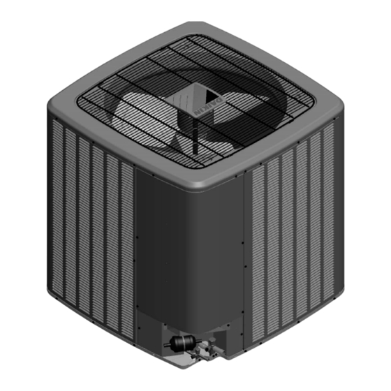
CONDENSING UNIT
DX9VC AIR CONDITIONING
INSTALLATION & SERVICE REFERENCE
Important Safety Instructions ............................1
Shipping Inspection ................................................2
Codes & Regulations ..............................................2
Features ...................................................................2
Installation Clearances .......................................2
Rooftop Installations ...........................................3
Safe Refrigerant Handling ..................................3
Refrigerant Lines ..................................................4
Refrigerant Line Connections ............................7
System Start-up Procedure .................................8
Electrical Connections ........................................8
Wiring Diagram ....................................................15
Testing Capacitor Resistance ............................18
Troubleshooting ..................................................22
Setting The Mode Display ...................................24
7-Segment Display ................................................30
Start-up Checklist ...............................................33
"IMPORTANT - This product has been designed and manufactured to meet ENERGY STAR criteria for energy
efficiency when matched with appropriate coil components. However, proper refrigerant charge and proper air
flow are critical to achieve rated capacity and efficiency. Installation of this product should follow the manu-
facturer's refrigerant charging and air flow instructions. Failure to confirm proper charge and airflow may
reduce energy efficiency and shorten equipment life."
© 2022
IOD-4041
12/2022
Our continuing commitment to quality products may mean a change in specifications without notice.
19001 Kermier Rd., Waller, TX 77484
Important Safety Instructions
The following symbols and labels are used throughout this
manual to indicate immediate or potential safety hazards. It
is the owner's and installer's responsibility to read and comply
with all safety information and instructions accompanying
these symbols. Failure to heed safety information increases
the risk of personal injury, property damage, and/or product
damage.
Also see "Meanings of Symbols" on page 4.
HIGH VOLTAGE
DISCONNECT ALL POWER BEFORE SERVICING
OR INSTALLING THIS UNIT. MULTIPLE POWER
SOURCES MAY BE PRESENT. FAILURE TO DO SO
MAY CAUSE PROPERTY DAMAGE, PERSONAL
INJURY OR DEATH.
ONLY PERSONNEL THAT HAVE BEEN TRAINED TO INSTALL,
ADJUST, SERVICE OR REPAIR(HEREINAFTER, "SERVICE")
THE EQUIPMENT SPECIFIED IN THIS MANUAL SHOULD
SERVICE THE EQUIPMENT. THE MANUFACTURER WILL
NOT BE RESPONSIBLE FOR ANY INJURY OR PROPERTY
DAMAGE ARISING FROM IMPROPER SERVICE OR SERVICE
PROCEDURES. IF YOU SERVICE THIS UNIT, YOU ASSUME
RESPONSIBILITY FOR ANY INJURY OR PROPERTY
DAMAGE WHICH MAY RESULT. IN ADDITION, IN
JURISDICTIONS THAT REQUIRE ONE OR MORE LICENSES
TO SERVICE THE EQUIPMENT SPECIFIED IN THIS
MANUAL, ONLY LICENSED PERSONNEL SHOULD SERVICE
THE EQUIPMENT.
IMPROPER INSTALLATION, ADJUSTMENT, SERVICING OR
REPAIR OF THE EQUIPMENT SPECIFIED IN THIS MANUAL,
OR ATTEMPTING TO INSTALL, ADJUST, SERVICE OR REPAIR
THE EQUIPMENT SPECIFIED IN THIS MANUAL WITHOUT
PROPER TRAINING MAY RESULT IN PRODUCT DAMAGE,
PROPERTY DAMAGE, PERSONAL INJURY OR DEATH.
DO NOT BYPASS SAFETY DEVICES
www.daikincomfort.com
INSTALLATION INSTRUCTIONS
WARNING
WARNING
WARNING
Advertisement
Table of Contents
Troubleshooting

Related Manuals for Daikin DX9VC


Summary of Contents for Daikin DX9VC
-
Page 1: Table Of Contents
CONDENSING UNIT Important Safety Instructions The following symbols and labels are used throughout this DX9VC AIR CONDITIONING manual to indicate immediate or potential safety hazards. It INSTALLATION & SERVICE REFERENCE is the owner’s and installer’s responsibility to read and comply with all safety information and instructions accompanying these symbols. -
Page 2: Shipping Inspection
Specification sheets can be found at www.daikincom- obstruction(s). The specified dimensions meet requirements fort.com for Daikin products. Within the website, please select for air circulation only. Consult all appropriate regulatory codes the residential or commercial products menu and then select prior to determining final clearances. -
Page 3: Rooftop Installations
RECOMMENDED Placement to Minimize Electronic Noise SAFETY CONSIDERATION While these items will not cover every conceivable Minimum Airflow Clearance situation, they should serve as a useful guide. Model Type Residential 10" 10" 18" 20" Read these Safety considerations for Installation carefully Light Commercial 12"... -
Page 4: Meanings Of Symbols
Refrigerant Lines WARNING CAUTION REFRIGERANTS ARE HEAVIER THAN AIR. THEY CAN “PUSH OUT” THE OXYGEN IN YOUR LUNGS OR IN ANY ENCLOSED THE COMPRESSOR PVE OIL FOR R-410A UNITS IS EXTREMELY SPACE. TO AVOID POSSIBLE DIFFICULTY IN BREATHING OR SUSCEPTIBLE TO MOISTURE ABSORPTION AND COULD CAUSE DEATH: COMPRESSOR FAILURE. -
Page 5: Burying Refrigerant Lines
0 - 250' Equivalent Line Set Length OTHER PROTECTION DEVICE IS SHORTED AND OPERATED FORCIBLY, OR PARTS OTHER THAN THOSE SPECIFIED BY Condensing Line Type DAIKIN ARE USED, FIRE OR EXPLOSION COULD RESULT. Unit & Line Diameter (In. OD) (Tons) Suct NOTICE •... - Page 6 Condenser BELOW Evaporator Mounting the evaportaor coil above the condensing unit will requre an inverted loop in the suction line adjacent or near the connection to the evaporator, for the purpose of creating an oil trap. The top of the loop must be slightly higher than the top of the coil.
-
Page 7: Refrigerant Line Connections
Refrigerant Line Connections Leak Testing (Nitrogen or Nitrogen-Traced) WARNING IMPORTANT: To avoid overheating the service valve, TXV, sensor, or filter drier while brazing, wrap the component with a wet rag, or use a thermal heat trap compound. Be sure to TO AVOID THE RISK OF FIRE OR EXPLOSION, NEVER USE follow the manufacturer’s instruction when using the heat OXYGEN, HIGH PRESSURE AIR OR FLAMMABLE GASES FOR... -
Page 8: System Start-Up Procedure
Deep Vacuum Method (Recommended) NOTICE The Deep Vacuum Method requires a vacuum pump ALL UNITS SHOULD HAVE A HIGH VOLTAGE POWER SUPPLY rated for 500 microns or less. This method is an effective CONNECTED 2 HOURS PRIOR TO STARTUP. and efficient way of assuring the system is free of non- condensable air and moisture. -
Page 9: High Voltage Connections
DEVICES. IF THE PRESSURE SWITCH, THERMAL SWITCH, OR OTHER PROTECTION DEVICE IS SHORTED AND OPERATED FORCIBLY, OR PARTS OTHER THAN THOSE SPECIFIED BY DAIKIN ARE USED, FIRE OR EXPLOSION COULD RESULT. • DO NOT CONNECT THE GROUND WIRE TO GAS PIPES,... - Page 10 Low voltage terminal C from indoor unit must connect to low voltage terminal C on thermostat and low voltage terminal R on thermostat. Verify wires are not reversed. NOTE: The order of the terminals of the indoor unit and the Daikin One+ Smart Thermostat are different. See System Wiring. •...
-
Page 11: Step 3. System Start-Up
Step 3. System Start-up to the following procedure. For a detailed procedure, please visit the Daikin One+ Smart a. If subcooling and superheat are low, adjust TXV to Thermostat website at http://www.daikinone.com. 8°F ± 1°F. superheat, then check subcooling. - Page 12 For effective dehumidification operation: • Ensure “dehumidification” is NOT set to “OFF”. - For detailed procedure to access the this function, please visit the Daikin One+ Smart Thermostat website at http://www.daikinone.com. • Verify the cooling airflow profile is set to “Profile D”.
-
Page 13: Error History
This is recommended for applications with unusually These advanced features are organized into a menu structure. cold return temperatures such as basements. For detailed functions and menu layout, please visit the Daikin One+ Smart Thermostat website at http://www.daikinone.com. Cooling Airflow Profile (cool profile) •... - Page 14 The system can have Dehumidification operation in setting “Standard”, “A”, “B” or “C” of “dehumidification” menu based on dehumidification demand. Setting “Standard” allows for the widest compressor operation range with lower CFM than Cooling mode. In the Enhanced Dehumidification (setting A, B and C) the indoor airflow is lower than Standard Dehumidification (Standard).
-
Page 15: Wiring Diagram
Wiring Diagram - 2-3 Tons DX9VCA2410**;DX9VCA3610** Wiring is subject to change. Always refer to the wiring diagram on the unit for the most up-to-date wiring. - Page 16 DX9VCA4810** Wiring Diagram - 4 Tons Wiring is subject to change. Always refer to the wiring diagram on the unit for the most up-to-date wiring.
- Page 17 DX9VCA6010** Wiring Diagram - 5 Tons Wiring is subject to change. Always refer to the wiring diagram on the unit for the most up-to-date wiring.
-
Page 18: Testing Capacitor Resistance
Testing Capacitor Resistance WARNING VOID CONTACT WITH THE CHARGED AREA •N EVER TOUCH THE CHARGED AREA BEFORE CONFIRMING THAT THE RESIDUAL VOLTAGE IS VOLTS OR LESS 1. S HUT DOWN THE POWER AND LEAVE THE CONTROL BOX FOR MINUTES 2. M AKE SURE TO TOUCH THE ARTH GROUND TERMINAL TO RELEASE THE STATIC ELECTRICITY FROM YOUR BODY TO PREVENT... - Page 19 Testing Capacitor Resistance WARNING VOID CONTACT WITH THE CHARGED AREA •N EVER TOUCH THE CHARGED AREA BEFORE CONFIRMING THAT THE RESIDUAL VOLTAGE IS VOLTS OR LESS 1. S HUT DOWN THE POWER AND LEAVE THE CONTROL BOX FOR MINUTES 2. M AKE SURE TO TOUCH THE ARTH GROUND TERMINAL TO RELEASE THE STATIC ELECTRICITY FROM YOUR BODY TO PREVENT...
- Page 20 Testing Capacitor Resistance WARNING VOID CONTACT WITH THE CHARGED AREA •N EVER TOUCH THE CHARGED AREA BEFORE CONFIRMING THAT THE RESIDUAL VOLTAGE IS VOLTS OR LESS 1. S HUT DOWN THE POWER AND LEAVE THE CONTROL BOX FOR MINUTES 2. M AKE SURE TO TOUCH THE ARTH GROUND TERMINAL TO RELEASE THE STATIC ELECTRICITY FROM YOUR BODY TO PREVENT...
- Page 21 COOLING ANALYSIS CHART POSSIBLE CAUSE X IN ANALYSIS GUIDE INDICATE "POSSIBLE CAUSE" Liquid stop valve does not fully open Gas stop valve does not fully open Line set restriction Line set length is too long Blocked filter-dryer OD EEV coil failure OD EEV failure ID EEV coil failure ID EEV failure...
-
Page 22: Troubleshooting
Troubleshooting NOTE: For detailed information on the unitary error codes, please visit the Daikin One+ Smart Thermostat website at http://www.daikinone.com. Outdoor Unit Dipswitch Default Factory Settings Switch # Setting Function Communication Termination Resistor Communication Termination Resistor Cooling Emergency Mode* Cooling Emergency Mode*... -
Page 23: Network Troubleshooting
Troubleshooting Network Troubleshooting If a network communication error has occurred, use the fol- lowing steps to help troubleshoot the system. (For network communication error codes, refer to the table below and the tables of error codes for outdoor unit and indoor unit.) After any wiring changes have been made or DS1 dip switches on the outdoor unit control board have been changed, apply power to the system and see if the error codes have cleared. -
Page 24: Setting The Mode Display
Setting The Mode Display MODE DISPLAY INTRODUCTION A 3-digit display is provided on the printed circuit board (PCB) as a backup tool to the thermostat for reading faults, fault history, monitoring and setting up the unit. Follow the information provided in this section to learn how to use the mode display. DISPLAY The display consists of 3 digits. - Page 25 Setting The Mode Display NAVIGATING THROUGH THE DISPLAY SCREENS SCREEN The home or default screen on the display. This shows the most recent fault. SCREEN 1 To access, hold the RECALL button for 5 seconds at screen 0. SCREEN 2 To access, hold the RECALL button for 5 seconds at screen 1.
- Page 26 Setting The Mode Display FAULT CODE HISTORY NAVIGATION < SCREEN 1> This mode will allow the user to see the six most recent system faults. For a list of the fault codes, please see the TROUBLESHOOTING tables in this document. <...
- Page 27 Setting The Mode Display MONITORING MODE NAVIGATION < SCREEN 0 > < SCR EEN 2 > This screen allows the user to monitor system variables as shown in the tables at the end of this section. Blink interval: < SCREEN 1 > 0.4 sec.
- Page 28 Setting The Mode Display SETTINGS MODE 1 NAVIGATION < SCREEN 3 > < SCREEN 0 > Setting Mode 1 allows the user to adjust system settings as shown in the tables at the end of this section. Blink interval: < SCREEN 2 > 0.4 sec.
- Page 29 Setting The Mode Display SETTINGS MODE 2 < SCREEN 4 > < SCREEN 0 > Setting Mode 2 allows the user to change system settings. See table in back of this section. Blink interval: 0.4 sec. On - 0.4 sec. Off <...
-
Page 30: 7-Segment Display
7-Segment Display SCREEN 0 (Display FAULT CODE) Setting Contents Notes Fault code (present) SCREEN 1 (Display FAULT CODES) Setting Contents Notes Fault code (latest) Latest Fault code (2nd) Fault code (3rd) Fault code (4th) Fault code (5th) Fault code (6th) SCREEN 2 (MONITOR MODE) Setting Contents... - Page 31 Screen 3 7-Segment Display Screen 3 (Setting Mode 1) Setting No. Contents Setting Installer/Serviceman Notes Cool Airflow Trim High *1,*2 0: -15% 2: -5% 4: 5% 6: 15% 1: -10% 3: 0% 5: 10% Cool Airflow Trim Int 0: -15% 3: 0% 6: 15% 9: Full (Max)
-
Page 32: Split Systems
SPLIT SYSTEMS AIR CONDITIONING AND HEAT PUMP HOMEOWNER’S ROUTINE MAINTENANCE RECOMMENDATIONS We strongly recommend a bi-annual maintenance checkup be performed before the heating and cooling seasons begin by a qualified servicer. Replace or Clean Filter Clean Outside Coil (Qualified Servicer Only) IMPORTANT NOTE: Never operate unit without a filter in- stalled as dust and lint will build up on internal parts resulting in loss of efficiency, equipment damage and possible fire. -
Page 33: Start-Up Checklist
Start-Up Checklist Condenser / Heat Pump (including all Inverter) Model Number Serial Number ELECTRICAL (Outdoor Unit) Line Voltage (Measure L1 and L2 Voltage) L1 - L2 Secondary Voltage (Measure Transformer Output Voltage) NOT ALL MODELS R - C Compressor Amps Condenser Fan Amps TEMPERATURES (Indoor Unit) Return Air Temperature (Dry bulb / Wet bulb) - Page 34 Troubleshooting ClimateTalk PCB LED Transmitted Thermostat Fault Probable Causes Corrective Actions Fault Code Display ClimateTalk Message ● High electrical noise OD CTRL FAIL1 Indicates a general memory error. ● Replace control board if necessary ● Faulty control board ● Blocked/restricted condenser coil and/or lines ●...
- Page 35 Troubleshooting This error indicates the equipment is experiencing Repair/replace as needed HI DISCH TEMP frequent high discharge temperature faults. Discharge thermistor is not put on correct position. The control has detected that the Discharge DISCH TEMP FAIL Temperature Sensor is out of range. Repair/replace as needed HPS OPEN The high pressure switch is open.
- Page 36 Troubleshooting Repair/replace if needed HIGH CURRENT Control Board detected a high current condition. The control encountered an abnormal condition STARTUP ERROR during the startup procedure. Indicates the control board may need to be OD CTRL FAIL4 Repair if needed replaced. The control has detected a voltage related issue utility if needed COMP VOLTAGE...
- Page 37 Troubleshooting ClimateTalk PCB LED Transmitted Thermostat Fault Probable Causes Corrective Actions Fault Code Display ClimateTalk Message ● Check and clean grille of any debris This error indicates the equipment is experiencing ● Obstruction in fan rotation ● Check wiring from Outdoor fan motor to control board; frequent outdoor control board and/or motor faults.
- Page 38 THIS PAGE INTENTIONALLY LEFT BLANK...
- Page 39 THIS PAGE INTENTIONALLY LEFT BLANK...
- Page 40 CUSTOMER FEEDBACK Daikin is very interested in all product comments. Please fill out the feedback form on the following link: https://daikincomfort.com/contact-us You can also scan the QR code on the right to be directed to the feedback page. PRODUCT REGISTRATION Thank you for your recent purchase.
Need help?
Do you have a question about the DX9VC and is the answer not in the manual?
Questions and answers