Table of Contents
Advertisement
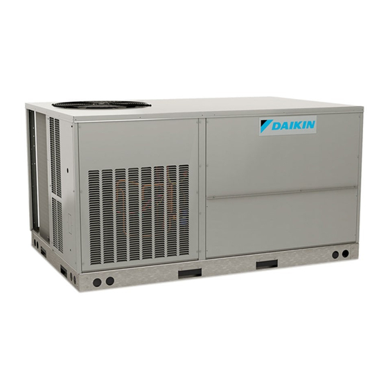
Service Instructions
DCC Cooling/DCH Heat Pumps
Commercial Package Units
with R-410A Refrigerant
4 - 6 Tons & Accessories
Not for installation in the United States or Canada. This unit is for export only.
This manual is to be used by qualified, professionally trained HVAC
technicians only. Daikin does not assume any responsibility for property
damage or personal injury due to improper service procedures or services
performed by an unqualified person.
RSDX6412006r1
November 2016
Copyright © 2015
-
2016
Advertisement
Chapters
Table of Contents


Need help?
Do you have a question about the DCH048 Series and is the answer not in the manual?
Questions and answers