Table of Contents
Advertisement
Quick Links
General Description
This guide provides a summary for installing and configuring the Centaur
be used in conjunction with the Centaur
TM
The Centaur
II Cube ASE directly supports up to four fire alarm panels or sprinkler systems, and another 12 systems via
Slave ASEs, each using an FAS input to send Alarm, Fault, and Isolate signals to the ASE. The ASE combines this information
together with its own status and sends it to a control and monitoring system (CMS) using a radio modem, telephone line, and/or
Ethernet link.
The ASE is powered from a fire alarm panel at 12 or 24Vdc.
Isolate/Test Key
or
Diagnostic Lead
Checking the kit
Before commencing installation, please ensure that the following items are present and undamaged:
1 x Centaur II Cube ASE with SIM card fitted
1 x plastic bag containing 1 x body plug and 4 screws for mounting the front cover
and that the backup PSTN line has been installed and tested.
The following will also be needed (provided separately to the ASE):
1 x antenna and lead
1 x phone lead
1 x Operating Instructions
FAS interface units FP0740/2/3 as required for each fire system.
Before applying power
-
Check that the circuit boards have received no visible damage during shipment and that the radio modem is firmly fitted.
-
Check the SIM card is fitted properly.
-
Connect the green earth wire from the termination board to the front panel J2 Earth Tab located in the bottom left corner.
-
Carefully fit the 20 way flat ribbon cable (FRC) from the front panel to the termination board. Take care to orient the FRC
pin 1 (the red wire) as shown in Fig 2 and thus insert the polarizing pin into the provided hole in the circuit board. Take
care not to break the polarising pin off.
-
Connect the aerial lead from the back box to the radio modem (refer to Fig 2).
Warning
Do not insert the micro SIM card with the power applied to the ASE. Always turn off the power before inserting or removing the
SIM.
LT0506 Issue 1.6
Centaur
TM
Alarm Signalling Equipment
INSTALLATION GUIDE
TM
Cube ASE User Manual (LT0508) and the commissioning guide.
Antenna
To 12V or 24V
power supply
(Usually fire alarm
panel)
To FAS relays
Fig 1 – General Layout
7 April 2015
II Cube
TM
Cube Alarm Signalling Equipment (ASE). It should
To Phone Line
To Ethernet plug
Page 1 of 10
Advertisement
Table of Contents

Related Manuals for ADT Centaur II Cube


Summary of Contents for ADT Centaur II Cube
- Page 1 Before commencing installation, please ensure that the following items are present and undamaged: 1 x Centaur II Cube ASE with SIM card fitted 1 x plastic bag containing 1 x body plug and 4 screws for mounting the front cover and that the backup PSTN line has been installed and tested.
- Page 2 FAS Connection There are three ways in which a fire alarm system can be connected to the Centaur II Cube ASE. The first is for a fire alarm panel that has 3 (or 4) relay outputs capable of signalling alarm, fault, and isolate. The fourth relay output is for "Standby"...
- Page 3 FAS 4+ Fig 3 - Connecting Centaur II Cube ASE to a Fire Panel using the FP0740 Interface Unit The FP0740 Interface unit is used to connect the Alarm, Fault and Isolate relays of a fire alarm panel to one FAS input on the ASE.
-
Page 4: Power Supply Connection
The Interface unit should be mounted within the alarm system enclosure and only the White wires should be extended beyond the enclosure. Note also that the Interface units have an IP51 rating and so should not be subjected to excessive moisture, or heat. Power Supply Connection The ASE will operate from a dc voltage in the range of 9V to 30V so it can be powered from a 12V or 24V fire alarm system without alteration. - Page 5 Ethernet Connection By default the Ethernet port is disabled and is configured via the ASE’s diagnostic port when required. For further details please refer to the Centaur II Cube ASE User Manual (LT0508). Location Card A small card can be slid into a slot on the front of the ASE to label the 4 inputs. This card should have the location of each input typed or written on it, as well as the ASE’s DTE number and fire brigade connection number.
- Page 6 Power up On power up the following should occur: LED self-test - all LEDs and the internal buzzer will turn on for approx 3 seconds then turn off. The POWER LED will turn on and remain on (except during the software version display). ...
-
Page 7: Input Button
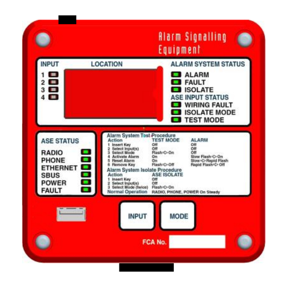
Tables 3 and 4 detail the meaning of the ALARM SYSTEM STATUS and ASE INPUT STATUS LED indicators. In both cases, an Input LED is lit to show which input has its status displayed. If only one input is off-normal, then its status will be displayed continuously. -
Page 8: Isolate Mode
Note that the mode button is enabled only when 1 or more INPUT LEDs are flashing. Any inputs that have been isolated by the CMS will be shown as being in Isolate Mode. You will not be able to select these inputs or change their Mode using the ASE buttons. - Page 9 ASE. Table 8 contains a list of basic commands available. For a detailed explanation of all diagnostic commands, refer to the Diagnostic Command Summary in the Centaur II Cube ASE User Manual, LT0508. Table 8 - Basic Diagnostic Commands...
-
Page 10: Specifications
Centaur II ASE, Diagnostic Lead Related Documents Centaur II Cube ASE Operator Instructions, LT0507 Centaur II Cube ASE User Manual, LT0508 Centaur II Cube Slave ASE Installation Guide, LT0518 Contact Details ADT Fire Monitoring Office: Telephone: 1300 360 575 Queensland / Victoria...
Need help?
Do you have a question about the Centaur II Cube and is the answer not in the manual?
Questions and answers