Advertisement
Document Number LT0543
General Description
This guide provides a summary for installing and configuring the Centaur
V5 software. It should be used in conjunction with the Centaur
TM
The Centaur
II Dual 3G ASE directly supports up to four fire alarm panels or sprinkler systems, and another 12 systems via
Slave ASEs, each using an FAS input to send Alarm, Fault, and Isolate signals to the ASE. The ASE combines this information
together with its own status and sends it to a control and monitoring system (CMS) using two radio modems.
The ASE is powered from a fire alarm panel at 12 or 24Vdc.
Antenna
To 12 V or 24 V
power supply
( Usually fire alarm
panel )
Checking the Kit
Before commencing installation, please ensure that the following items are present and undamaged:
1 x Centaur II Dual 3G ASE
1 x plastic bag containing 2 x body plugs, 3 x 4 way plugs and 4 screws for mounting the front cover.
The following will also be needed (provided separately to the ASE):
2 x antenna and lead
1 x Telstra SIM card
1 x Optus SIM card (backup radio link)
1 x Operating Instructions
FAS interface units FP0740/2/3 as required for each fire system.
Before Applying Power
-
Check that the ASE has received no visible damage during shipment.
Check the SIM cards are fitted properly.
-
Connect the aerial leads from the back box to the radio modems (refer to Fig 2).
-
Warning
Do not insert the micro SIM cards with the power applied to the ASE. Always turn off the power before inserting or removing the
SIMs.
V5 Software
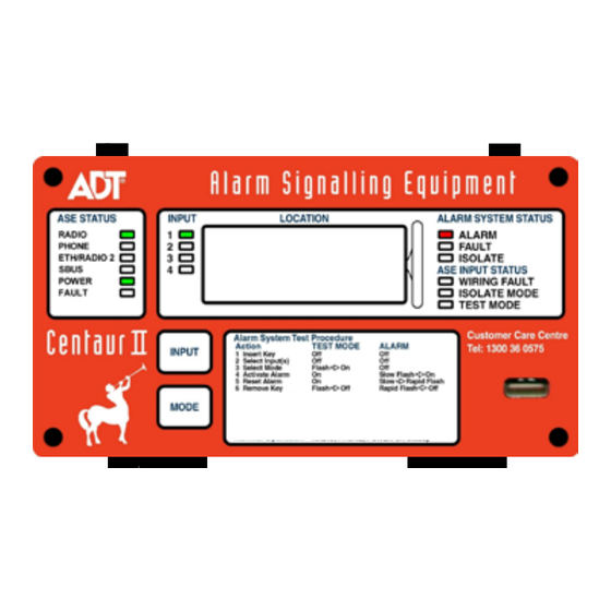
With V5 software the Key Isolate function has been removed from the ASE, as it is not permitted under AS 1670.3:2018. A
white label has been fitted to the front label to cover the description of the Key Isolate function.
LT0543 Issue 3.0
Centaur
II Dual 3G
TM
Alarm Signalling Equipment
INSTALLATION GUIDE
TM
II ASE User Manual (LT0508) and the commissioning guide.
To FAS relays
Fig 1 – General Layout
31 March 2020
Centaur II Dual 3G Installation Guide
TM
II Dual 3G Alarm Signalling Equipment (ASE) with
Backup Antenna
Test Key or
Diagnostic Lead
To Phone Line
To Ethernet plug
Page 1 of 10
Advertisement
Table of Contents

Related Manuals for ADT Centaur II Dual 3G


Summary of Contents for ADT Centaur II Dual 3G
- Page 1 Before commencing installation, please ensure that the following items are present and undamaged: 1 x Centaur II Dual 3G ASE 1 x plastic bag containing 2 x body plugs, 3 x 4 way plugs and 4 screws for mounting the front cover.
- Page 2 If the signal strength indication is too low, the antenna must be repositioned and/or changed. The required RSSI level is dependent on the type of radio modem being used. Refer to ADT Fire Monitoring commissioning requirements for the particular value.
- Page 3 Document Number LT0543 Centaur II Dual 3G Installation Guide FAS Connection There are three ways in which a fire alarm system can be connected to the ASE. The first is for a fire alarm panel that has 3 (or 4) relay outputs capable of signalling alarm, fault, and isolate. The fourth relay output is for "Standby"...
-
Page 4: Power Supply Connection
Document Number LT0543 Centaur II Dual 3G Installation Guide Connection of a Fire Alarm System with Alarm Contacts Only Centaur II FP0742 Fire Alarm System Interface White Orange N/O Alarm FAS + Unit Orange White Fig 4 - Connecting ASE to a N/O Fire Alarm System using the FP0742 Interface Unit... -
Page 5: Open Collector Outputs
Document Number LT0543 Centaur II Dual 3G Installation Guide Open Collector Outputs Two open collector outputs (transistor pull down, 100mA max to 0V) are available for controlling relays or local indications (e.g., buzzer or LED) to signal pre-determined conditions. They should be powered from the ASE’s +V, not from external equipment, so as to maintain electrical isolation. -
Page 6: Diagnostics And Testing
Document Number LT0543 Centaur II Dual 3G Installation Guide Diagnostics and Testing The 12 Status LEDs and four input selection LEDs indicate the status of the ASE and the configured FAS inputs. Table 2 details the status or fault conditions shown by each of the ASE STATUS LEDs. Additional and more detailed diagnostic information is available from the Diagnostic Port using a laptop or computer. - Page 7 Document Number LT0543 Centaur II Dual 3G Installation Guide Table 3 – ALARM SYSTEM STATUS LED Indicators Label Colour LED State Description Displayed input not in alarm. Rapid Flash In Test Mode only: Test Alarm was acknowledged by the monitoring system and input is no longer in alarm.
-
Page 8: Rssi Display
Document Number LT0543 Centaur II Dual 3G Installation Guide The ASE will remain in Test Mode until the key is removed or Test Mode times out after 4 hours. If the key is removed, and in input is in alarm, the ASE will beep and flash the TEST MODE LED for 15 seconds. Reinserting the key during the 15 second period will restart Test Mode with a new timeout and prevent the alarm from being sent to the CMS. - Page 9 Document Number LT0543 Centaur II Dual 3G Installation Guide Logging Off Radio Networks If a SIM card is to be changed it is necessary to log the ASE off the radio networks before the ASE is powered down and the SIM is changed.
-
Page 10: Specifications
FP0802 Centaur 12V 0.5A PSU Box FP0976 Centaur II ASE, Diagnostic Lead Related Documents Centaur II Dual 3G ASE Operator Instructions, LT0544 Centaur II ASE User Manual, LT0508 Centaur II Slave ASE Installation Guide, LT0520 Contact Details ADT Fire Monitoring...
Need help?
Do you have a question about the Centaur II Dual 3G and is the answer not in the manual?
Questions and answers