Table of Contents
Advertisement
Quick Links
Advertisement
Table of Contents

Related Manuals for Kromek RAYMON10


Summary of Contents for Kromek RAYMON10
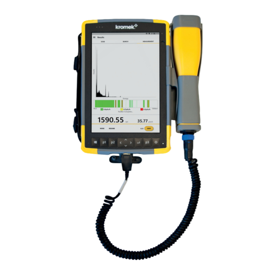
- Page 1 RAYMON10 USER MANUAL www.kromek.com...
- Page 2 The Kromek logo, RayMon, RadBar, MultiSpect and MultiSpect Analysis are registered trademarks of Kromek Limited. The information in this manual describes the product at the time of going to press and is subject to change without notice. Kromek frequently releases new software and hardware revisions and this manual may differ slightly from what is seen.
-
Page 3: Table Of Contents
Contents Warnings and Disclaimers ....................4 Section 1: Unpacking and Charging ..................6 Section 2: Device Navigation ....................8 Section 3: Power Up and Shutting Down................11 Section 4: Connecting a Detector Probe ................13 Section 5: Energy Calibration ..................... 14 Section 6: Stored Background .................... -
Page 4: Warnings And Disclaimers
Alarms on the device are determined by the counts per second (CPS) and not the dose rate. All parts for the RayMon device must be supplied by Kromek Ltd or its authorised agents. The RayMon device should not be opened or taken apart by the end user, any attempts to do so will void any warranty. - Page 5 Do not open the device, if the battery needs to be replaced, the RayMon device should be returned to Kromek Ltd. Opening the unit will void any warranty. Do not disassemble/open, crush, bend/deform, puncture/shred.
-
Page 6: Section 1: Unpacking And Charging
Section 1: Unpacking and Charging 1) Remove from packaging. 2) Select the appropriate outlet adapter for your AC wall outlet. 3) Connect the adapter to the charger by sliding into position until you hear a click. 4) Plug the charger into the wall outlet. - Page 7 5) Plug the barrel end of the charger into the power port on the bottom of the RayMon. 6) While charging the red LED in the top left-hand corner of the unit will blink on and off and the battery symbol in the top right-hand corner of the screen will show the battery filling up.
-
Page 8: Section 2: Device Navigation
Section 2: Device Navigation... - Page 9 Connector Ports inside access panel (from left to right on image directly above): Microphone/Speaker Jack USB 3.0 Host, Full Size 12 VDC Power Input Jack...
- Page 10 The RayMon can be navigated by tapping the on-screen buttons using your finger or the stylus provided. Options provided on the bottom of the screen can be selected either by tapping them on- screen or by pressing the corresponding button (p1, p2 or p3) on the keypad below the option you which to select.
-
Page 11: Section 3: Power Up And Shutting Down
Section 3: Power Up and Shutting Down 1) Press and hold the Power key for a few seconds. Pressing the Power button once briefly will turn the screen off. Press the Power button once briefly again to turn the screen back on, once the screen appears with the date and time press a finger to the bottom of the screen and move it to the top if the screen. - Page 12 3) After initialisation the DOSE screen is displayed showing the counts per second (CPS) and the live dose rate in either µSv/h or mrem/h. The RayMon can be navigated by tapping the on-screen buttons using your finger or the stylus. Options provided on the bottom of the screen can be selected either by tapping them on-screen or by pressing the corresponding button (p1, p2 or p3) on the keypad...
-
Page 13: Section 4: Connecting A Detector Probe
Section 4: Connecting a Detector Probe The RayMon will work with different detector probe types connected via USB. Probes can be swapped at any time and RayMon will automatically adjust to the type of probe connected. All user settings on the device, except for the energy calibration and background radiation spectrum, are retained regardless of which probe is connected. -
Page 14: Section 5: Energy Calibration
Section 5: Energy Calibration The calibration screen can be accessed from the drop- down Main Menu, by clicking on the three horizontal lines located above the DOSE header (highlighted in the image opposite). Select Calibration from the drop-down Main Menu. Two calibration methods are provided. - Page 15 Auto Calibration 1) Point the probe at a Cs-137 calibration source and press the AUTO button. Accepting the AUTO calibration values will clear all the existing points from the previous calibration(s) (including any calibrations that were manually added). 2) The device will acquire for as long as is necessary to collect enough counts for analysis.
- Page 16 Manual Calibration Calibrations are generally performed with sealed sources such as: Source Gamma-ray energy 60 keV 662 keV Other sources can be used or added if available. However, a minimum of two gamma rays must be used for an adequate calibration. 1) Place the source in front of the detector and press MANUAL.
- Page 17 3) Once the manual calibration scan has been stopped, the assign screen will appear. 4) Press on the graph and then zoom onto the peak (refer to Section 2, for zoom and graph manipulation instructions). Note that the Channel number above the graph will change as the cursor is moved.
- Page 18 5) Single tap the screen to place the yellow cursor line on the centroid of the peak relating to the source. 6) Press on the 0 underneath Energy and enter the energy in keV of that source using the top-up keyboard. Then press ASSIGN.
- Page 19 7) The Calibration screen will be displayed. The REPEAT button allows multiple peaks from the same measurement to be used by repeating steps 3 to 6, or steps 1 to 6 can be repeated for a second source. A straight line is fitted through the calibration points and the calibrated values used in the device are displayed at the bottom of the page.
-
Page 20: Section 6: Stored Background
Section 6: Stored Background The device uses a stored background spectrum as a reference in some algorithms. The spectrum can be accessed from the Main Menu drop-down, by clicking Background. 1) The measure time can be adjusted if desired by pressing the numbers below Measure Time and using the pop-up keyboard to make the necessary changes. - Page 21 2) While the background is being measured the yellow bar at the bottom (under the cps value) shows the progress. To finish the measurement early press STOP. 3) After the background has been acquired or you have pressed STOP, a message will appear stating Do you want to save this background? Pressing OK will save the new background scan.
- Page 22 4) Once all the necessary changes have been made press the arrow in the top left-hand corner (to the left of the Background title) to return to the DOSE screen.
-
Page 23: Section 7: Dose Setup And Cps Alarm
Section 7: Dose Setup and CPS Alarm 1) Open the Main Menu drop-down and press Dose Settings. 2) Enter the required Integration Time by pressing the numbers below the Integration Time header and using the pop-up keyboard to make the necessary changes. The default value is 10 seconds... - Page 24 3) Enter the required Update Time by pressing the numbers below the Update Time header and using the pop-up keyboard to make the necessary changes. The default value is 10 seconds. 4) Enter the required CPS Alarm by pressing the numbers below the CPS Alarm header and using the pop-up keyboard to make the necessary changes.
- Page 25 5) When the count rate exceeds the alarm value the top bar and the cps value will turn red, also a red message will appear stating Counts Above Threshold. 6) The Units used by the RayMon can be configurated between SI (dose in µSv/h) or US Standard (dose in mrem/h) using the drop down box.
-
Page 26: Section 8: Search Mode
Section 8: Search Mode 1) From the main DOSE screen press the SEARCH header in the top middle of the screen. 2) Search mode works by comparing the measured total counts from the detector in a fast response channel (red line) to a background level (blue line). - Page 27 If the measured counts exceed the background level by a significant amount, the user is alerted to the possible presence of a radiation source by the cps value turning red and the graph being given a red shading. 3) To configure the settings with regards to the search mode open the Main Menu drop-down and press Search Settings.
- Page 28 4) Auto-Track On If the background is set to Auto-Track in the setup, a slow rolling average of the counts is maintained. The background integration time should be long compared to the fast integration time. The default is 60 seconds. It is not recommended to use values below 20 seconds.
- Page 29 6) Auto-Track Off The alternative to an auto-tracked background is to use the device’s Background scan as a constant reference level. Tap the toggle beside Auto-Track, so that it turns grey (off mode), when Auto-Track is turned off the device automatically using the device’s Background scan.
-
Page 30: Section 9: Measurement Setup
Section 9: Measurement Setup 1) Open the Main Menu drop-down and press Measurement Settings. 2) The Measurement Settings screen is split into the sections as you scroll down the page: ➢ Measurement settings ➢ Analysis settings ➢ RadBar settings... - Page 31 4) Select either Use live time or Use real time. Real time is the total time of the measurement. Live time is the length of time that the pulse processing hardware has been active and been able to detect pulses during the data acquisition.
- Page 32 6) The scaling of the RadBar can be configured by selecting one of the options within RadBar settings: • To Max adjusts the scale so the highest value in any bin is at the top of the scale. • Fixed applies a constant scale, configurable in dose units of µSv/hour or mrem/hour.
- Page 33 8) The Confidence Limit parameter is used when calculating the upper and lower bounds for net counts in a peak region. Press on the confidence limit box to change the value. The default value is 95.00%. 9) The Peak ROI Width determines the width of the peak region used for analysis calculations.
- Page 34 10) The Lower Level Discriminator (LLD) value cannot be altered. It is the threshold below which the detector’s electronics cannot register a signal and is determined by the firmware on the detector. 11) If Auto save is selected to be on (toggle is yellow), each measurement will automatically be saved and identified by the date and time of the measurement.
- Page 35 13) Pressing on the Analysis Setup button will open the Analysis Setup Isotope Library, so that the library can be set up as required before a scan is started. Pressing the arrow in the top left hand corner beside the Raymon10 header, returns back to the Measurement Settings screen.
-
Page 36: Section 10: Making A Measurement
Section 10: Making a Measurement From main DOSE screen press MEASUREMENT header in the top middle of the screen. 2) The MEASUREMENT screen will be displayed. Press START to begin collecting data. - Page 37 3) The data collection will continue until the set duration time (either real or live as selected) is reached, as long as RadBar is turned off, if RadBar is turned on the times may differ to those set (as discussed in Section 9, Step A time counter is displayed beside the START/STOP button and a yellow progress bar is shown near the bottom of the screen, just above the timer.
- Page 38 5) On-screen graphs: ▪ Zoom in by placing your thumb and index finger together on the screen over the area you want to zoom into and then move your fingers apart. ▪ Drag the graph to view another region of the graph by placing one finger on the screen over the graph and moving your finger across the screen (this will move the cursor).
- Page 39 7) If the user decides to SAVE the scan, the Reports screen will be displayed. The user can add Notes, view the recorded Location, and Add a photo (picture should be taken in a landscape orientation for optimal viewing in the exported report). To take a picture, press on the Add a photo section, a camera image will then appear on the screen, simply press the screen to take the photo.
-
Page 40: Section 11: Opening A Saved Measurement
Section 11: Opening a Saved Measurement 1) Open the Main Menu drop-down and press Reports. 2) Measurements are sorted by date and time, with the most recently taken at the top of the list. - Page 41 3) The list can be filtered, with a rough time frame from the drop-down menu, options are: ➢ ➢ Today ➢ Yesterday ➢ This Week ➢ This Month ➢ This Year If you select Yesterday, it will show every scan taken between now and up to the beginning of yesterday, not just the scans taken yesterday.
- Page 42 5) Single press on the scan to open the report. 6) To view the spectrum and RadBar (if that was turned on for this scan), press the SPECTRUM button.
- Page 43 7) Pressing MORE, allows the user to review the Identify, Analyse and Activity (only available if the user has purchased this option). If a feature was not turned on during the scan, for instance, if Identify was not turned on during the scan, this will appear greyed out on the list so that it cannot be selected as there will be no data available.
-
Page 44: Section 12: Radionuclide Id
Section 12: Radionuclide ID Note that Identification must have been turned on in Measurement Settings for the scan taken for these functions to be available. The energy calibration must also be accurate. 1) Once a measurement scan is complete the results screen will be displayed. - Page 45 To return to the Results press the arrow next to the Raymon10 header at the top of the screen. 4) If more counts are required in the spectrum press RESUME to collect more data in the existing spectrum.
-
Page 46: Section 13: Spectral Analysis For Advanced Users
Section 13: Spectral Analysis for Advanced Users After making a measurement or loading a previously saved measurement the spectrum can be analysed. 1) Press the MORE option in the bottom-left of the screen to display the analysis options. Pressing Analyse displays the analysis results. - Page 47 3) The results can be filtered by pressing the filter symbol (highlighted opposite) in the top-right corner of the screen. 4) The Minimum intensity can be changed, allowing only strong emission lines from a radionuclide to be shown where the relative intensity is greater than the value stated (in this case >50%).
- Page 48 5) If the Minimum intensity is increased or decreased you may see more or less radionuclides in the list. In the example opposite the Minimum intensity has been reduced to 10%. 6) The filter can also be used to Show all energy lines or only Energy lines above the critical limit.
- Page 49 8) Pressing the arrow in the top-left of the screen beside the Raymon10 header will display the graph with the energies displayed in the results table (using the filters set) identified by blue regions on the graph.
-
Page 50: Section 14: Analysis Setup
Section 14: Analysis Setup 1) Change the default Analysis Setup applied to all future measurements, can be achieved by going to pressing Analysis Setup button found Measurement Settings. Alternatively, to change the analysis for the current data, after the results are displayed choose, go to the Analysis Results table (see Section 13 for instructions) and then press SETUP at the bottom of the screen. - Page 51 2) To turn on a category for analysis, press the greyed toggle beside the categories needed for analysis, so that it turns on (turns yellow). In the example opposite, the Industrial category is turned on while the other categories are turned off. 3) Press the downward arrow to see all the isotope included in the category and which ones are currently turned on.
- Page 52 4) To turn individual isotopes on/off, simple hit the toggle button so it is either yellow for on or grey for off. 6) If an isotope has multiple lines, these can be individually selected and enabled or disabled as required. Press the cog symbol beside the category and press Open.
- Page 53 Then press the cog symbol (highlighted opposite), beside the isotope and press Open. To turn individual isotope lines on/off, simple hit the toggle button so it is either yellow for on or grey for off.
- Page 54 7) The cog symbol at the very top of each screen allows you to Select All and Select None, this will turn all the toggles on or off, that are on that screen. 8) Pressing View from a cog allows the user to view all energy lines that...
- Page 55 If none of the energy lines have been selected but the isotope is turned on a message under the isotope will appear stating None Selected.
-
Page 56: Section 15: User Defined Categories And Nuclides
Section 15: User Defined Categories and Nuclides 1) If required the user can define a customised category by pressing the top cog in the Analysis Setup screen and then pressing Create Category. 2) A Create Category window will appear, enter a category name and press OK. - Page 57 3) Press the cog in the top-right corner and press Add Isotope. 4) Scroll down through the isotope list and turn the toggle on (yellow) for all the isotopes that need to be included in the user category. Once all the isotopes have been selected press OK.
- Page 58 This will automatically take you back to the User Category screen, which should now list the categories selected. 5) As with the default categories, individual lines within an isotope can be enabled or disabled as required. Open the isotope from the cog and turn the individual energy lines toggles on/off as required.
- Page 59 8) If an isotope is required that is not in the built-in the library, it can be added manually. Press the cog in the top-right corner and press Create Region. A Create Region window will appear, enter a region name and press OK. 9) Press the cog in the top-right corner and press Create Line.
- Page 60 10) Press the number below Centroid Energy and enter the energy, then press the number below Background Window, then Background Window and ROI information will then automatically fill in. The default background window is 3 keV either side of the peak. This value can be changed by selecting the Background Window number and then entering the desired value in keV.
-
Page 61: Section 16: Software Upgrade
Calibration will become greyed as they are inoperable function without the probe being connected. 2) Plug the USB containing the software into the USB port of the RayMon10. An Upgrade option should now appear at the bottom of the Main Menu drop down. - Page 62 3) An Upgrading… window will appear. A message box will then appear asking: Do you want to allow this app from an unknown publisher to make changes to your device? Underneath this message it should state the software it is intending to install, check that it states: Raymon the version number.exe (e.g.
-
Page 63: Section 17: Pin Code Locking
Section 17: PIN Code Locking The RayMon can be in either locked or unlocked mode. The functions allowed when the device is locked can be chosen by the user and can only be changed by entering a four digit PIN code. When the device is unlocked all functions are enabled, the unit is shipped unlocked. - Page 64 To lock the device 3) In the Main Menu, and press Feature Control. 4) Review the list of features that are either turned on (yellow toggle) or turned off (grey toggle). If a feature is turned on it means it is available to the user when the device is locked.
- Page 65 To change the PIN code 5) The RayMon must be unlocked to be able to change the PIN. In the Feature Control screen, press PIN at the bottom of the screen and then enter the old PIN and press OK. 6) Enter the new PIN and press OK.
- Page 66 7) Re-enter the new PIN and press OK. 8) A PIN Update message box will appear when the update is complete.
- Page 67 9) In the Main Menu, press Unlock Features and when the Unlock Device window appear, press Reset. 10) Enter the reset password provided by Kromek and then press OK to reset the PIN to 0000. A PIN Reset message will appear when the process is...
-
Page 68: Section 18: Sharing Reports
Section 18: Sharing Reports 1) To share a report a WiFi connection is required. Press the Windows key on the keypad, on the bottom bar, press on the WiFi symbol on the bottom taskbar and connect to your WiFi network. Press onto the Search header to when you have connected to your WiFi network. - Page 69 3) If this is the first time a report has been shared the user will have to set up/sign in to an email account or an account in another sharing App. Follow the on-screen instructions to set this up. Once an account is set up, press on the sharing apps logo, in this example we are going to share via Mail and send an email.
- Page 70 6) Once the report has been sent the sharing app will close. Press DONE in the report to close it.
-
Page 71: Section 19: Usb Data Export
Section 19: USB Data Export 1) In the Main Menu, and press Reports. 2) Filter the reports so that only the reports you want to export are in the Reports list. Unplug the probe and plug in a USB memory stick. Press the cog in the top-right of the screen and press Export. - Page 72 3) Once the export is complete, the Report Export, should state Complete. The reports will be saved to a folder called Raymon, in the USB memory stick. They will be organised in date and then time folders.
-
Page 73: Appendix 1: Radionuclides In The Library
Appendix 1: Radionuclides in the library The following nuclides are included in the RayMon nuclide library. Categorisations are taken from the standard ANSI N42.34 – 2006. Additional nuclides have been added to each category that may be of use to the user. Category Nuclides Included †... -
Page 74: Appendix 2: Technical Specification
Appendix 2: Technical Specification... - Page 75 For after-sales and customer service enquiries please use the following contacts T: +44 (0) 1740 626060 E: service@kromek.com MAL-OPS-0938 Rev 2.0...
- Page 76 Kromek Group plc UK NETPark Thomas Wright Way Sedgefield TS21 3FD | +44 (0) 1740 626060 USA 143 Zehner School Road Zelienople PA 16063 | +1 724 352 5288 sales@kromek.com www.kromek.com...
Need help?
Do you have a question about the RAYMON10 and is the answer not in the manual?
Questions and answers