Table of Contents
Advertisement
Quick Links
Advertisement
Table of Contents

Related Manuals for CTC Union GW211W-MB


Summary of Contents for CTC Union GW211W-MB
- Page 1 User Manual GW211W-MB Modbus RTU to Modbus TCP Gateway sales@ctcu.com...
- Page 2 8F, No. 60 Zhouzi St., Neihu, Taipei 114, Taiwan T +886-2-26591021 F +886-2-26590237 E sales@ctcu.com H www.ctcu.com 2022 CTC Union Technologies Co., LTD. All trademarks are the property of their respective owners. Technical information in this document is subject to change without notice.
-
Page 3: Table Of Contents
Table of Contents INTRODUCTION ....................... 4 OVERVIEW ....................... 5 PACKAGE CHECKLIST ....................5 PRODUCT SPECIFICATIONS ..................6 PRODUCT PANEL VIEWS ................... 8 ............................8 NTENNA ..........................10 ERIAL NTERFACE LED INDICATORS ....................11 WIRING ARCHITECTURE ..................12 CONFIGURATION ....................13 IP S ......................... -
Page 4: Introduction
Introduction GW211W-MB RTU/ASCII to TCP Gateway provides the easy way of connecting Modbus Serial devices to Wireless and Ethernet LAN in Modbus TCP and RTU/ASCII networks at the same time. The wireless supports 802.11 b/g/n in AP/Station mode with WEP/WPA/WPA2 encryption for data transmission security. Ethernet support 10/100 Mbps auto-detecting communication speeds. -
Page 5: Overview
Meters and/or Sensors to an IP-based Wi-Fi LAN, and makes it possible to access Serial interface devices anywhere and anytime via your software. GW211W-MB provides TCP Server Mode, TCP Client Mode, and UDP Mode for selection. It supports manual configuration via web browser and support various protocols including TCP, IP, UDP, HTTP, DHCP, ICMP, and ARP. -
Page 6: Product Specifications
Product Specifications System CPU: MT7688AN MIPS CPU, 580 MHz RAM: 128M Bytes DDR2 RAM ROM: 32M Bytes Flash ROM OS: OpenWrt Linux OS TCP to RTU support 8 simultaneous TCP Master, 32 simultaneous requests per Master. ... - Page 7 Serial Ports *2 Port: RS-232 *1 (RS-232 with RX/TX/GND only) Port: RS-422 / 485 *1 (Surge Protection) Speed: 300 bps ~ 921.6 K bps Parity: None, Odd, Even, Mark, Space Data Bit: 5, 6, 7, 8 ...
-
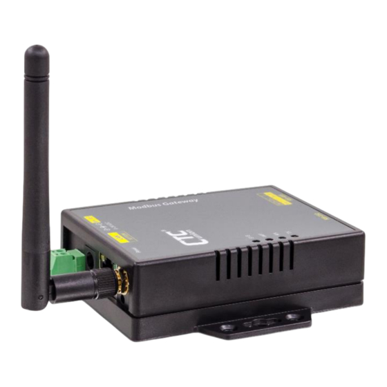
Page 8: Product Panel Views
Product Panel Views Antenna Side DC-IN Power Outlet Ethernet (DC Jack) LAN port Antenna DC-IN Power Outlet (Terminal Block) Reset Push Button (beneath the antenna) DC-IN Power Outlet The Serial to Ethernet+WiFi Converter is powered by a single 12V DC (Inner positive, outer negative) power supply and 1A Current. - Page 9 Reset Button (1) Press reset key after 5 seconds until SYS LED flash then release the key will reset network default IP and gateway IP back to default. The other parameters keep same as last confirmation. (2) Press reset key after 5 seconds until both SYS LED and WiFi LED flash then release the key will make all parameters back to factory default.
-
Page 10: Serial Interface Side
Serial Interface Side RS-232 RS-422/485 Serial Port of RS-232/RS-422/RS-485 Connect the Serial data cable between the device and the Serial interface device. Follow the procedure of web page configuration to set up parameters. -
Page 11: Led Indicators
LED Indicators SYS (Green): Power indicator. When the power is on, the LED will be on and blink per second. WiFi (Red): WiFi indicator. When the WiFi is working, this LED will be blinking. Tx (Green): Data sending indicator. When data sends to the device from LAN or WiFi, this LED will blink. -
Page 12: Wiring Architecture
Wiring Architecture 1. RS-232 2. RS-422/RS-485 When you complete the steps mentioned above, the LED indicators will be lit. This means that the converter is connected and installed correctly. To proceed with the parameters setup, please use a web browser (IE or Chrome) to configure the detailed settings. -
Page 13: Configuration
Configuration When setting up your Gateway for the first time, the first thing you should do is to configure the IP address. You can use IP Device Search tool to find the IP or simply use the default IP to login to the device. The following topics are covered in this chapter: ... - Page 14 4. “Device Search” will pop up on the screen after installation or you may double click the icon on desk top of host computer to open this tool. 5. Click on “Find” button. It will scan the network and show up the IP of Gateway. 6.
- Page 15 7. Click “Goto” button will open a web page of configuration. (Default Username: admin; Default Password: admin). 8. You can also use the default IP address (10.1.1.1) to login to the configuration webpage with the default Username: admin and Password: admin. Note: The default Ethernet IP address is 10.1.1.1/24;...
- Page 16 9. When you successfully login to the device, the following main screen will pop up.
-
Page 17: Web Browser Configuration
Web Browser Configuration There are 4 setup pages as “System”, “Network”, “Serial” and “Gateway”. System Setup 1. System: where you can change Password, set up Auto Reset time and modify Device Name, Description of device. 2. Appearance of Wireless and Ethernet setup. Please note that the default WiFi IP address is 10.0.0.1/24 and the default Ethernet IP address is 10.1.1.1/24. - Page 18 3. NTP: Enable / Disable NTP function; Set up NTP server and Time Zone. 4. Firmware update: If necessary, click “Browse” to open file manager. Then, select the file with specified version and click “open” button. When the selected file name appears on the input column, click “Update” button.
-
Page 19: Network Setup
5. Up to now, Setup is successfully configured. Please click “Save” and go to other pages for configuration or click “Save and Restart” to run new configuration. Network Setup 1. Wireless section: 1.1 Type: Click to select “Access Point” or “Infrastructure”. “Infrastructure” is for connecting to a local Router. - Page 20 1.2 If “ACCESS POINT” is selected, input password (1234567890) for the AP and assign IP address with “DHCP” or “STATIC”. 1.3 When “ACCESS POINT” is selected, this Device acts as an Access Point which is allowed to be connected by PC /NB /Smart Phone/ PAD. It supports DHCP server function.
- Page 21 1.4 Password: Key in password for the selected AP. 1.5 Encrypt...
- Page 22 1.6 Mode: select “DHCP” to let AP assign IP address to itself, or select “STATIC” to input assigned IP address, Subnet Mask manually. 1.7 If “Infrastructure” type is selected, set SSID of Router and the other inputs.
- Page 23 1.8 Go to item SSID, click “Scan” will get list of available SSID of Access Points, select the one in your network to link. For example: 1.9 On the NB/PC, choose same SSID to link. NB/PC must disconnect Ethernet in advance otherwise the data transmission would not work.
- Page 24 3. Gateway and DNS section: check with MIS for right IP address of Ethernet or Wi-Fi. The Gateway must be set with the correct IP enable to connect with other devices. 4. Up to now, Setup is successfully configured. Please click “Save” for this page temporarily and go to other pages for configuration or click “Save and Restart”...
-
Page 25: Serial Port Setup
Serial Port Setup Please clearly set each parameters from Serial 1 to Serial 2 (Default 9600, n, 8, 1). Baud Rate: 300 bps to 921.6K bps Parity: None, Even, Odd Data Bits: 5, 6, 7, 8 Stop Bits: 1, 2 Flow Control: None, XON/XOFF RxDelay(ms) TxDelay(ms) -
Page 26: Gateway Setup
Gateway Setup 1. There are Modbus Serial” #1 and #2 over TCP/IP. 2. Gateway Type: 4 types for selection or to disable this function. - Page 27 3. For TCP Client, users can set up to 8 clients. 4. Up to now, Setup is successfully configured. Please click “Save” and go to other pages for configuration or click “Save and Restart” to run new configuration. 5. After configuring all parameters, click “Save and Restart” to reboot system.
-
Page 28: Testing Verification
Testing Verification After completing the wiring and parameter setting, we should verify if the setting is correct. This chapter will introduce how to use a single computer to test whether the converter work well. The operating system can be Window 7/8/10. The “Hyper Terminal” utility should be installed on host PC/NB. - Page 29 2. Key in a file name of connection (eg. test) and then click “OK”. 3. Choose TCP/IP, then click “OK”. 4. Key in the Converter’s IP address and Socket port then click “OK”. *for testing RS-232: default Port Number is 100 *for testing RS-422/485: default Port number is 101...
- Page 30 5. A HyperTerminal window will show up. The time counter start at the down left corner if connect is correct.
-
Page 31: Hyper Terminal For Com Port
6. Echo Loop Test For RS-232 testing: Short DB9 connector #2 pin and #3 pin as circuit. For RS-422 testing: Short the green Terminal Block T+ to R+ and T- to R- or TX to RX. In RS-422/485 setup page: choose RS422 firstly. ... -
Page 32: Reset Push Button
Reset Push Button (1) Press reset key for 5 seconds or longer until SYS LED flash. Then, releasing the reset key will reset network default IP and gateway IP back to default settings. The other parameters remain the same as the last confirmation. (2) Press reset key for 5 seconds or longer until both SYS LED and WiFi LED flash. -
Page 33: Pin Assignment
Pin Assignment DC Power outlet RS-232 Pin Assignment The pin assignment scheme for a 9-pin male connector on a DTE is given below. PIN 1 : DCD PIN 2 : RXD PIN 3 : TXD PIN 4 : DTR PIN 5 : GND PIN 6 : DSR PIN 7 : RTS PIN 8 : CTS... - Page 34 Date Version 2022/9/30 V1.0 (202101a) Preliminary version (outsourced)
Need help?
Do you have a question about the GW211W-MB and is the answer not in the manual?
Questions and answers