
Related Manuals for MindMedia NeXus Q32


Summary of Contents for MindMedia NeXus Q32
- Page 1 User manual 30-0006-0005 REV 7.1 Last update: 2024-06-04 Caution: Federal (USA) law restricts this device to sale by or on the order of a physician or licensed practitioner...
-
Page 2: Table Of Contents
ABLE OF ONTENTS SERVICE AND SUPPORT About this manual Contact information Mind Media Warranty information Additional accessories or spare parts Abbreviations SAFETY INFORMATION Explanation of markings Limitations of use and contra-indications Warnings and precautions Disclosure of residual risk Information for lays Connection to an IT-network General advice PRODUCT OVERVIEW... - Page 3 Perform Ambulatory Measurement Impedance Measurement Recovery of lost data Status Events Operational Principles NeXus Q Device Unipolar input channels Bipolar (ExG) input channels Auxiliary input channels Tips for obtaining optimal quality data MAINTENANCE Servicing and Updates Cleaning instructions Disposal instructions ELECTROMAGNETIC GUIDANCE Degradation of performance Electromagnetic emission...
-
Page 4: Service And Support
1.2 Contact information Mind Media Mind Media B.V. (MM) Support can be reached via email (support@mindmedia.com) or via the website: www.mindmedia.com. Please provide as much information as possible, including serial numbers of the used products. This will help to support you in the best way possible. -
Page 5: Additional Accessories Or Spare Parts
1.4 Additional accessories or spare parts In case you want to order additional accessories such as cables or sensors or spare parts such as batteries, please contact info@mindmedia.com for consultation and a detailed quotation. 1.5 Abbreviations Abbreviation Auxiliary Bipolar Break-Out-Box Conformité... -
Page 6: Safety Information
2 SAFETY INFORMATION This section contains general warnings, explanation of markings, limitations of use, safety measures, and precautionary measures that are important for the safe use of the product. 2.1 Explanation of markings This section explains the various markings and symbols used with the product. Warning: read important safety information Caution Consult instructions for use... -
Page 7: Limitations Of Use And Contra-Indications
Stand-by symbol Power status indicator; see chapter 3.4 Remote Interface status indicator; see chapter 3.4 2.2 Limitations of use and contra-indications The following limitations of use are applicable due to relevant regulations and to ensure the device is able to perform as specified throughout this user manual. Limitations of use ●... -
Page 8: Disclosure Of Residual Risk
Warnings and precautions Only use patient accessories explicitly approved by MM to avoid the risk of electric shock. Do not connect equipment that is not IEC 60950 compliant to NeXus Q to avoid the risk of electric shock. Do not touch pins of removed batteries or of disengaged connector plugs or sockets to avoid the risk of electric shock. -
Page 9: Connection To An It-Network
● Which indicators, if any, must be monitored, how often, and how to react on specific status indications. ● Event marker When to press the button. ● Specifically: how batteries must be exchanged and recharged, if they're running out. ● Contact the (medical professional) user when an unexpected situation or problem occurs. - Page 10 Advice Remove batteries from NeXus Q if it is not likely to be used for some time. To prolong battery life, store them preferably at 40 % charged state and at a temperature in the range (-20 to 20) °C. To avoid signal disturbance, keep NeXus Q away from sources of strong electric, magnetic and electromagnetic radiation.
-
Page 11: Product Overview
The product is intended to be used with approved electrodes and sensors which can be found on the MM website www.mindmedia.com. Please refer to the instructions for use of those electrodes and sensors, if applicable. 3.2 Intended use... - Page 12 Patient interface and operating principle The product amplifies and stores signal data picked up via electrode leads or sensors that are connected to a single patient or subject; no data interpretation is performed. Intended use of this product does not require expected positions of the user or patient. No essential consumables are required for the intended use of this product, however commercially available disposable electrode patches and/or contact gel can be used for contact between electrode and patient skin.
-
Page 13: Product Views
Only use the product with the supplied parts and accessories. In case other parts or accessories are required, contact MM (info@mindmedia.com) for information. Expected service life The expected service life of the device is 7 years. If the product is intended to be used after its expected service life, it is recommended to contact MM to have the product inspected before continued use. -
Page 14: Front View
Docking station Description Arrow indicating direction for docking Data Recorder Docking connector (pins) Docking rails to guide and secure Data Recorder to the Docking Station Fiber connector (behind cover) Status indicator window Front View Marking Description AUX 1-3 Auxiliary input connectors ExG 1-4 Bipolar input connectors for ExG measurements Patient Ground connector... -
Page 15: Bottom View
Docking rails to guide and secure Data Recorder to the Docking Station Bottom View Docking Station Description Gutters for docking on the Bracket Device label Dock security ribbon for the Bracket Data Recorder Description Docking connector (contact points) Gutters for docking on the Docking Station or Bracket Device label Page 15 of 53... -
Page 16: Back View
Dock security ribbon for the Bracket Back view Part Description Data Recorder Event marker button Data Recorder Release buttons for battery compartments Docking Station Trigger connector (behind cover) Docking Station USB status indicator Docking Station USB connector Docking Station Ethernet status indicator Docking Station Ethernet connector Docking Station... -
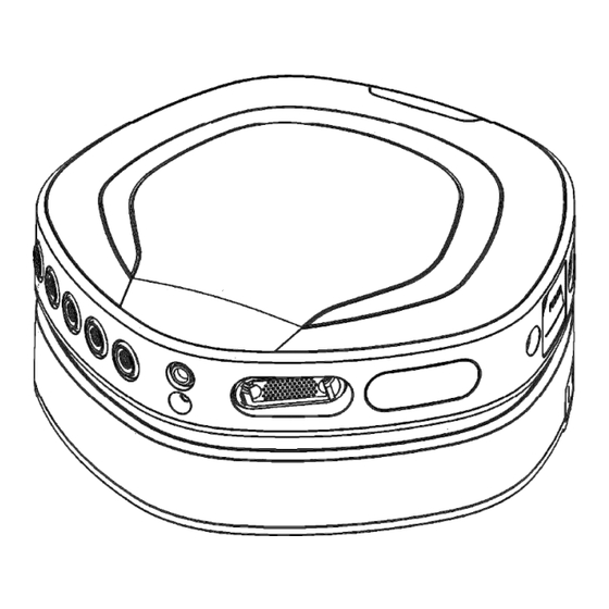
Page 17: Side Views
Side views Part Description Data Recorder SYNC OUT connector Data Recorder Fiber connector (behind cover) Data Recorder Recording button Data Recorder ON/OFF button Docking Station Fiber connector (behind cover) Data Recorder CAP multi-connector Part Description Data Recorder Digital input connector (DIGI) Data Recorder Auxiliary input (AUX 1-3) connectors Data Recorder... -
Page 18: User Interface
3.4 User interface Data Recorder Connections Type Function Connects the Data Recorder to the Docking Station for power supply Docking connector and data transmission Connects the Data Recorder to the Docking Station for optical data Fiber connector transmission Patient connections General Unipolar Bipolar... - Page 19 Status Indicators Indicator Function and states ● OFF: average reference mode ● GREEN (solid): common reference mode ● ORANGE (solid): common reference not available ● ORANGE (blinking): common reference disconnected after start recording, Reference Mode Device switched to average reference mode. ●...
- Page 20 Docking Station Connections Type Function USB connector Primary data interface to PC Ethernet connector Secondary data interface to PC (Disabled by default) Trigger connector 16-bit trigger input to acquire signals from external equipment Fiber connector Connector for an optical fiber for data interface with a Data Recorder Power connector Supply power from Mains power adapter to Docking Station Docking connector...
-
Page 21: Patient Connections
Lights The lights on the backside of the Docking Station can have the following states. Lights Function ● OFF: Docking Station is off Power ● GREEN (solid): Docking Station is switched on ● OFF: the ethernet interface is not available Ethernet ●... -
Page 22: Auxiliary Inputs
difference of which is recorded. The device supports up to 4 bipolar channels, accessible via two bipolar input connectors with two bipolar channels each. An electrode lead may have one pair of electrodes or two pairs of electrodes. Accessories (leads) connected to the bipolar inputs may provide a type identification that can be read out via the application software interface. -
Page 23: Device Labels
The SYNC OUT port requires a synchronisation out cable which can be ordered via info@mindmedia.com. The DIGI input and SYNC OUT output are electrically isolated within the device from all other Data Recorder inputs and the patient. - Page 24 device specific information is an impression of the actual information that is found on the label. The UDI-DI and serial number together also provide the human readable Unique Device Identification (UDI). The medical device name (MD) describes the exact device variant or model. Note: the numbers in between brackets, next to UDI-DI and SN, are application identifiers for the UDI and not part of the reference or serial number.
-
Page 25: Spare Parts - Order Information
NeXus Q (see Section 9) and are designed to operate safely with this device. More information about approved patient accessories is available on www.mindmedia.com. Other types of patient accessories may become available. Refer to the respective Mind Media product information and instructions for use to determine if the accessory is approved for use with... -
Page 26: Instructions For Use
4 INSTRUCTIONS FOR USE 4.1 Power the Docking Station Plug the mains power plug into a well-earthed mains socket and connect the mains power adapter output connector to the Docking Station. Make sure you use the correct orientation. When you insert the connector, you will hear a ‘click’. -
Page 27: Battery Low Indication
Battery change during measurement Batteries can be exchanged during measurement. Please note that to continue the recording without interruption, there should always be at least one -sufficiently charged- battery inserted while exchanging batteries. When the device is not acquiring data, the ON/OFF button also powers down the Data Recorder. During a measurement, the Data Recorder will not power down by means of the ON/OFF button. -
Page 28: Docking Mechanism
4.4 Docking mechanism Establish an electrical connection between Data Recorder and Docking Station by sliding the Data Recorder in the Docking Station. Align the docking rail of the Docking Station and the gutters on the bottom of the Data Recorder. See illustrations below. The wired connection indicator in the status indicator windows will light up green when the connection is made correctly. -
Page 29: Data Connections
along the axis of the plug to operate a retention mechanism. To make a connection, observe the alignment symbols and gently push the plug into the socket of the NeXus Q device. To disconnect, take hold of the plug at its moving sleeve, the part closest to the socket, and gently pull the plug out. Do NOT pull at the accessory wire or at the wire end of the plug. -
Page 30: Software
USB memory stick optionally provided with the device. Please contact info@mindmedia.com. Run the device driver setup and follow the steps on screen. Depending on the acquired Application Software, the driver installation may be performed automatically as part of its installation. Refer to its instructions of use to verify compatibility with the acquired device type. -
Page 31: Perform A Measurement
ERFORM A MEASUREMENT NeXus Q supports a variety of usage scenarios: ● Streaming data in stationary use (5.1) ● Streaming data in portable setting via wireless connection (5.2) ● Streaming data in portable setting via optical fiber (5.3) ● Ambulatory recording without data streaming (5.4) 5.1 Perform Stationary Measurement The stationary measurement setup consists of a setup where the data acquisition PC and measurement device are at a fixed place and do not move throughout the experiment. -
Page 32: Perform Portable Measurement Using Wireless Connection
5.2 Perform Portable Measurement using Wireless connection In the portable measurement setup, the Data Recorder is undocked from the Docking Station and the Wi-Fi link is used for data transmission. This setup is optimal for usage scenarios where freedom of movement is an important requirement. The data from the Data Recorder is sent through Wi-Fi to the Docking Station. -
Page 33: Bandwidth Management
Data backup logging During a measurement via a wireless data connection, the Data Recorder will log the measurement data on its on-board memory card as backup. Lost data can be retrieved after the measurement has been finished. Refer to chapter 5.6 for more detailed instructions on recovery of lost data. -
Page 34: Perform Ambulatory Measurement
5.4 Perform Ambulatory Measurement In an ambulatory measurement setup, the Data Recorder is used as a data logger without the function of data streaming. The data is logged on the on-board memory and can be downloaded from the on-board memory afterwards. Note that in this setup the Trigger input on the Docking Station is not available. -
Page 35: Impedance Measurement
Multiple ambulant recordings with the same configuration can be present on the internal memory. Always make sure to download all important measurement data before a new measurement is started or configuration is changed using the PC, because this will erase all data present on the internal memory of the Data Recorder. -
Page 36: Status Events
● Switch the Data Recorder ON and wait until the Wi-Fi connection to the Data Recorder is restored. Now the measurement data can be repaired. In case the measurement is interrupted because the data acquisition PC or docking station shuts down due to a major power supply cut or user error, the Data Recorder may continue to acquire data on its on-board memory. -
Page 37: Trigger Input
Ambulatory data Device 0 = See ‘Sample data’ below 1 = Present data packet contains ambulatory data Sample data Device 0 = See ‘Ambulatory data’ below 1 = Present data packet contains live data TrigOk/reliable Device 0 = Data Recorder data and Trigger input data is not/badly synchronized 1 = Synchronization between Data Recorder data and Trigger inputs is reliable... -
Page 38: Battery Low
The digital input is an isolated input where a low-voltage TTL level signal (LVTTL) can be used to mark specific time points. The trigger is sample synchronous to all the other data. Refer to chapter 9 detailed information regarding input and output signals and allowed levels. Battery low The Data Recorder runs on one or two batteries. -
Page 39: Operational Principles
PERATIONAL RINCIPLES 6.1 NeXus Q Device NeXus Q is an amplifier for electrophysiological measurements designed for optimal signal quality. The NeXus Q amplifier is characterized by low input noise, high input impedance and high common mode rejection. It is a true DC reference amplifier with high resolution and uses active signal shielding to minimize electrode cable capacitance and thereby minimizes cable movement artefacts and sensitivity to mains interference (50/60 Hz). -
Page 40: Bipolar (Exg) Input Channels
6.3 Bipolar (ExG) input channels The bipolar inputs of NeXus Q are designed to measure electrophysiological parameters such as EEG, ECG, surface EMG or EOG, using two electrode connections per bipolar input. The inputs are configured as a differential amplifier with as output the difference in potential between the two electrodes. - Page 41 Electrode materials NeXus Q is a DC-coupled amplifier with a high input range of +/-150 mV. This is more than sufficient for common measurement setups. The electrode-skin interface will act as a battery which causes a DC-shift in the signal of several millivolts up to a few hundred. If all electrodes, including patient ground, are made of the same material, this will not be a problem at all.
-
Page 42: Maintenance
Bug fixes or improvements to the firmware may become available for download from the website (www.mindmedia.com). This update can be performed by the user. Follow the instructions accompanied with the update package carefully. Not complying with these instructions may cause the device to become unusable. -
Page 43: Electromagnetic Guidance
8 ELECTROMAGNETIC GUIDANCE 8.1 Degradation of performance Electromagnetic disturbances, such as electrostatic discharge, mains supply overvoltage spikes and mains interruptions may cause the following types of degradation of performance: ● Noticeable artefacts on signals. These should be discarded because they are clearly non-physiological signal traits. -
Page 44: Electromagnetic Emission
8.2 Electromagnetic emission Guidance and manufacturer’s declaration - electromagnetic emissions The product is intended for use in the electromagnetic environment specified below. The customer or the user of the product should assure that it is used in such an environment. Emission test Compliance Electromagnetic environment - guidance... - Page 45 Guidance and manufacturer’s declaration - electromagnetic immunity The product is intended for use in the electromagnetic environment specified below. The customer or the user of the product should assure that it is used in such an environment. Immunity test IEC 60601-1-2 test level Compliance Electromagnetic environment - guidance level...
- Page 46 Guidance and manufacturer’s declaration - electromagnetic immunity The product is intended for use in the electromagnetic environment specified below. The customer or the user of the product should assure that it is used in such an environment. Immunity test IEC 60601-1-2 test level Compliance Electromagnetic environment - guidance level...
-
Page 47: Technical Specifications
9 TECHNICAL SPECIFICATIONS General Specifications Type NEXUS-Q32-DR Data Recorder NEXUS-Q-DS Docking Station REF# NEXUS-Q32-DR 70-0006-0001, 70-0006-0002 NEXUS-Q-DS 00-0005-0001 ᴓ 179 mm, height: 41 mm Size (device only) Data Recorder: ᴓ 179 mm, height: 47 mm Docking Station: Weight Data Recorder: 0.7 kg (excluding batteries) Docking Station: 0.7 kg... - Page 48 Battery Batteries 1 or 2 batteries Power Saving 30 minutes (idle, no connection to PC & undocked) Battery low indication 3.3 V level Battery empty shut down 3.1 V level Brand, type RRC power solutions, RRC1130 For further information including specification, refer to Manual, Data Sheet www.rrc-ps.com and label of the battery.
- Page 49 Temperature -20 °C to +60 °C Humidity 15 % to 90 %, non-condensing Pressure 600 hPa to 1100 hPa Storage Conditions Temperature 0 °C to +40 °C Humidity 15 % to 90 %, non-condensing Pressure 600 hPa to 1100 hPa Usage Conditions Temperature Data Recorder (alone): +5 °C to +40 °C...
- Page 50 Analogue bandwidth DC to 800 Hz at highest sampling rate, 0.4 * sampling rate otherwise Anti-alias filter 1.6 kHz low-pass Impedance Mode Separate mode, including patient ground impedance measurement 0 kΩ to 499 kΩ, special values are: 500 kΩ: overflow, the channel impedance is ≥500 kΩ...
- Page 51 Anti-alias filter 2.1 kHz low-pass Auxiliary Channel Specifications Number of channels 9 (3 x triple channel input) Output Voltage +5 V, max 45 mA for all channels together RMS noise <20 µV (0.1 to 100) Hz Input Range -3 V to +3 V Resolution <...
- Page 52 Electrical DIGI input SYNC OUT TRIGGER IN TRIGGER OUT Voltage range 0 to 3.3 0 to 6 0 to 5.5 0 to 3.3 ≤1 ≤1 ≤0.8 ≤0.5 Low level ≥2.3 ≥(Vs-0.5*V) ≥2.4 ≥2.7 High level Current @ High [mA] -0.5 to 0.5 -1 to 0 -0.5 to 0.5 -1 to 1 Current @ Low...
- Page 53 Channel Overview Name Connection Remarks CREF REF and UNI 1-32 UNI 1 to UNI 32 UNI 33 to Not available UNI 64 BIP 1 ExG 1 2 BIP 2 BIP 3 ExG 3 4 BIP 4 AUX 1.1 AUX 1 AUX 1.2 AUX 1.3 AUX 2.1...
- Page 54 Caution: Federal (USA) law restricts this device to sale by or on the order of a physician or licensed practitioner...
Need help?
Do you have a question about the NeXus Q32 and is the answer not in the manual?
Questions and answers