
Related Manuals for Siemens Sintony 60


Summary of Contents for Siemens Sintony 60
- Page 1 Wireless and hardwired intrusion control panel IC60 - Sintony 60 Installer Manual Building Technologies Fire Safety & Security Products...
- Page 2 Copyright Copyright 2007 © Fire & Security Products GmbH & Co. oHG. All rights reserved. Siemens Fire & Security Products GmbH & Co. oHG confers upon the purchaser the right to use the software. It is not permitted to reproduce this manual in whole or in part or translate it into another language without our written consent.
-
Page 3: Table Of Contents
Zone input configurations hardwired............15 1.2.2 Zone wiring examples ................16 Inputs hardwired..................17 System Bus connection-Keypad Port .............18 Programming Port ...................19 Extension modules for Sintony 60 control panel........19 1.6.1 Output module 12V/1A IRO6-04 (Output 5-8) ........19 1.6.2 Zone expander module IZE6-04 .............19 1.6.3 Radio receiver IRFW6................19... - Page 4 3.6.8 Manual answer an incoming call .............34 System settings of the LCD Keypad ............34 3.7.1 LCD backlight adjustment ...............34 3.7.2 Keypad button backlight adjustment ............34 3.7.3 Volume adjustment of the keypad buzzer..........34 How to program the Alarm System .............35 Programming the system by PC .............35 Programming the system remotely ............35 Programming the system be Memory stick..........35 Programming the system trough a Keypad..........35...
- Page 5 Miscellaneous panel and timing settings...........50 Installer code...................50 Duress digit .....................50 Dial report delay ..................50 Radio zone supervised timer ..............50 Two trigger timer ..................51 Mains fail reporting delay ................51 receiver fail delay-timer................51 Upload-Download site code number............51 Temporary output disable ...............52 Miscellaneous installer and panel options.........53 Miscellaneous panel options..............53 Miscellaneous installer options ...............54 Miscellaneous user options..............54...
- Page 6 Key-switches ..................78 14.1 Key-switch wiring ..................78 14.2 Key-switch area assignment ..............78 14.3 Key-switch arm-disarm options ...............79 Zones......................80 15.1 Zone area assignment ................80 15.2 Zone type options- basic information ............80 15.3 Special Zone type options...............83 15.4 Different End of Line (EOL) Resistor value options ........84 15.5 Vibration sensor zone type- zone response time........85 15.6...
- Page 7 Contact ID Code Summary..............109 21.1 Change Zone Contact Identification (CID) report codes.......109 21.2 Change Keypad panic, fire and medical alarms CID report code..109 21.3 Contact ID Code Summary ..............110 Diagnostic and default options ............111 22.1 Display software version -keypad numbers and keypad areas ....111 22.2 Display active zones and battery voltage ..........111 22.3...
-
Page 8: System Overview
System overview System overview Sintony 60M modular Connection Diagram Fig. 1 The wiring option shown here with a common Tamper input (Tamp/Gnd) is not allowed in all countries, if the installation has to be done according to legal requirements (e.g. Belgium/INCERT).To integrate the Tamper contact directly into each zone input, see also chapter Zone wiring examples. -
Page 9: Battery Connections
System overview Battery Connections Connect a sealed lead acid rechargeable 12VDC battery to the terminals labeled red and black on the control panel being careful to observe the correct polarity. The maximum recommended battery capacity is 7 amp hours. Battery charge current at these terminals is limited to 600mA maximum. -
Page 10: Sintony 60 Compact
System overview Sintony 60 compact Connection Diagram IC60 compact overview Fig. 2 Connection Diagram IC60 compact 1 Fig. 3 In factory settings the jumper is set between COM & GND. The com contact can be connected to 12V by setting the jumper. - Page 11 System overview Connection Diagram IC60 compact 2 Fig. 4 Power for detectors & accessories Jumper for bypass Tamper in Line Bypassed Not Bypassed- requires Resistor EOL INPUTS Z1…Z16 Power for detectors & accessories Connector for internal siren (could be disconnected during installation) LCD pin header for Horizontal configuration Building Technologies Fire Safety &...
- Page 12 Programming Port RJ11 Linie-IN Phone Linie IN Phone Line Out Battery Specifications for Sintony 60 compact Ni-MH Rechargeable Battery 12V/1.8Ah. Battery Cutoff Level: (When AC mains fail): 10.5±0.1V. Full charge after 48 hours. The current limit over charge is 260mA.
- Page 13 System overview Battery Connections Place the Battery in its location, and secure it with the rubber band (see drawing). Connect the Battery plug into its connector (Refer to Fig, 3 Connection Diagram IC60 compact 1) General Specifications: The range of the "12V Out" which is used for feeding sensors is between 10.2 to 14.3V DC (working on mains or standby battery) .Ripple up to 0.1V p.p.
- Page 14 (Special wiring required ask your local country agent). The Mains' input cable has to be secured with a special cable clamp as per the following drawing: AC cable fixing Sintony 60 compact Fig. 7 AC connection port Sintony 60 compact Fig.
-
Page 15: Zone Connections
2k2Ω (Red, Red, Red) for Tamper To overtake existing installation with already build in different resistor values, the Sintony 60 could also be programmed to different values (see function P125E, End of line Options) NOTE: If an Input is programmed as a wireless input, the system will ignore all hardwired connection to this input and look only for the radio signal! (Programming function “zone A option”... -
Page 16: Zone Wiring Examples
System overview 1.3.2 Zone wiring examples The connection of each device depends on the type of switch which is used in the detectors. We differentiate between: N/C normally closed, requires serial connection N/O normally open, requires parallel connection Option 1: Only one EOL- end of line resistor Type 1-11 - Single EOL no Tamper Fig. -
Page 17: Inputs Hardwired
Inputs hardwired Earth Connection For the Sintony 60 compact connection, the Earth lead of the mains supply has to be connected. In case of the IC60 modular, if using metal box, the mains earth has to be connected to the appropriate terminal on the mains terminal block in the control box cabinet. -
Page 18: System Bus Connection-Keypad Port
Bus devices use to communicate with the Sintony 60. The terminals are connected to corresponding terminals on the remote devices. The "LIN" terminal is only used by the keypads and utilizes a fifth wire to provide a communicator “listen-dialing”... -
Page 19: Programming Port
1.7.1 Output module 12V/1A IRO6-04 (Output 5-8) With this extension PCB the Sintony 60 could be extended with additional 4 Relays to a maximum of 8 Outputs. Each relay could switch a max. power of 12V/1A. The connection to the Sintony 60 control panel is realized over the system bus. -
Page 20: Contact Less Card Reader Iar6-30 For Keypad Bus Connection
125kHz band. Its functionality is identical to a keypad and therefore it is programmed into the system as a standard keypad. In total maximum 8 keypads/card readers can be connected to a Sintony 60 control panel (Sintony 60 compact has one build in already- e.g. 7 more). -
Page 21: Output For Electrical Door Lock Control
This helps to save cabling. The reader output can only control the electrical lock! The Sintony 60 is not able to supply power for an external lock. An additional external power supply is recommended depending on the type of door lock which is used. -
Page 22: Lcd Keypad
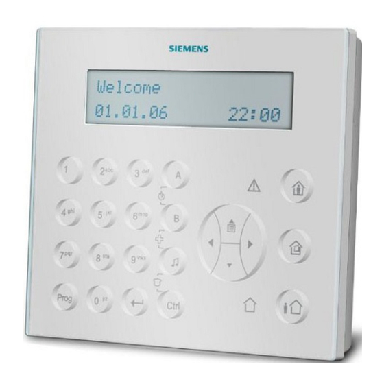
LCD Keypad LCD Keypad To operate the Control Panel Sintony 60 you need a Keypad which allows you to program and manipulate the systems and show all information on a big LCD Display in clear text. This Keypad is already included in the Sintony 60 compact version, where it works in the Sintony 60 modular as a separate stand alone unit with Bus connections. -
Page 23: Lcd Keypad Installation
LCD Keypad Installation Bus connection The connection to the Sintony 60 control panel is realized over the system bus. It is an intelligent member of the Bus with a unique Bus address (refer to Keypad Set up). It could be installed external to the Sintony 60 Control Panel (modular and compact version). -
Page 24: Accessing Local Program Mode
LCD Keypad 3.3.1 Accessing Local program Mode To enter Local program Mode on a LCD Keypad Press “CTRL” followed by “ARM” Hold for 2 seconds. The display will now show “Local Mode kb #” where the # equals the keypad address. -
Page 25: Local Program Mode Direct Program Addresses
LCD Keypad Menu Tree Fig. 17 When you are at the desired main menu heading, press <ENTER> to access the data program location. 3.3.3 Local program Mode Direct Program Addresses To access directly to the address via the Keypad buttons, without scrolling trough all the menu points you can use a shortcut by adding they following addresses directly. -
Page 26: Exiting Local Edit Program Mode
LCD Keypad 3.3.4 Exiting Local Edit Program Mode Press and hold the <PROG> button for 2 seconds and the LCD keypad will leave Local program mode and return to normal Mode or; Press the <PROGRAM> button repeatedly until the display reads “Exit Programming”, then press the <ENTER>... -
Page 27: Lcd Keypad Address Assignment
LCD Keypad 3.4.2 LCD Keypad Address Assignment A total of 8 devices (keypads or proximity readers) can be connected to the control panel. Each keypad must be addressed individually to avoid BUS conflicts when multiple users are operating different keypads simultaneously. By default, each keypad comes addressed as KP # 1. -
Page 28: Changing Names - Personalization Of The System
LCD Keypad Changing names – personalization of the system To make the Sintony 60 an individual system that fits exactly to the environment of the user, we recommend changing the general names to Object-related, easy to identify wordings. e.g. instead of showing only “Alarm in Zone 1” at the display the LCD text could be individualized to “Alarm Kitchen”, or “Keypad Office”... -
Page 29: Changing The Keypad Name
“Panel Name” or go directly by pressing {PROG}-[999]-[ENTER], the display will look like this: Name <A.Z> Siemens You may enter any name you wish up to 16 characters in length (using the same method as described in changing names). -
Page 30: Changing The Zone Names
LCD Keypad 3.5.4 Changing the Zone Names When in “Local Program Mode”, you scroll with the buttons <up>/ <down> to the position “Zone Name” or go directly by pressing {PROG}-[1]-[ENTER], the display will look like this: Zone 1 <A.Z> Zone 1 You may enter any name you wish up to 16 characters in length (using the same method as described in changing names). -
Page 31: Changing The Area Single Character Identifier
LCD Keypad 3.5.7 Changing the Area Single Character Identifier When in “Local Program Mode”, you scroll with the buttons <up>/ <down> to the position “Area Id” or go directly by pressing {PROG}-[998]-[ENTER], the display will look like this: Area ID <A.Z> ABCDEFGHIJKLMNOP You may edit the single character Area identifier at this address starting at Area “A”... -
Page 32: Operating A Lcd Keypad
LCD Keypad Operating a LCD Keypad 3.6.1 LCD Keypad View Memory Mode When displaying Memory Events in “Memory Mode” the Display will show the events using plain text messages with the time & date that the event occurred. This makes the fault diagnosis much easier. All events can be displayed (including when the system was disarmed and by whom). -
Page 33: Lcd Quick View Mode
LCD Keypad 3.6.4 LCD quick view mode If any zones are unsealed when disarmed the LCD keypad will scroll through each unsealed zone displaying the 16 character name for each zone. If a number of zones are unsealed simultaneously it can take sometime for the display to show all of the unsealed zones. -
Page 34: Manual Answer An Incoming Call
LCD Keypad 3.6.8 Manual answer an incoming call If the panel is not configured to answer in-coming calls, the user can force it to answer the call by pressing and holding <CONTROL> followed within 2 seconds by <9>. This will make the panel answer the call immediately. For this function to work the phone line must be ringing at the time and there must have been at least two rings before pressing the buttons. -
Page 35: How To Program The Alarm System
How to program the Alarm System How to program the Alarm System To program the Control Panel the System can be programmed in 4 different ways locally or remotely trough a telephone line connection. Programming the system by PC With the separate available programming cable IAQ6-1 and the programming Software “Sylcom 60”... -
Page 36: Access To Installer Program Mode
How to program the Alarm System 4.4.1 Access to Installer program mode To get into installer program mode the system must be disarmed. Press <PROG> Enter Master code (default is 258369) <ENTER> When you enter the Installer program mode the LCD Keypad display automatically “INSTALLER:USER”. -
Page 37: Keypad Menu Programming
How to program the Alarm System 4.4.4 Keypad Menu Programming The LCD Keypad enables “Manual Free” programming of the SINTONY 60 panel. Easy to follow plain text Menus will be displayed on the keypad to enable selection of the desired programming options. -
Page 38: Stepping Back Through The Menus
How to program the Alarm System 4.4.9 Stepping Back Through the Menus If you are in a Menu location, e.g. the “USER” Data Entry field, and you wish to step back one stage to the previous Sub-Menu, you need to press the <PROGRAM>... -
Page 39: Programming Codes
Programming codes Programming codes To use the following described programming codes the System has to be in Installer program mode. How to read the programming codes is described in chapter Keypad code programming- How to program with a LCD Keypad. How to read the programming codes is described in chapter Keypad code programming- How to program with a LCD Keypad. -
Page 40: Programming Users
Programming users Programming users User codes P1E 1-100E The user codes are located in address P1E 1-100E NOTE: Only users 21-100 can be Radio Users 7.1.1 Adding or changing a User Code Up to 100 codes can be programmed into the panel. By default, Code 1 has Master Code permissions and must be used to enter Client program mode. -
Page 41: User Code Type
Programming users User code Type USER CODE TYPE - P2E 1-100E 0-8E NOTE: only Users 21-100 can be Radio Users Option Description Keypad Code User {PIN} - All 100 Users can be 1-6 digit code Users if required. Codes can be used to Arm/Disarm all or part of the alarm or they can be used to operate outputs for access control purposes. -
Page 42: User Access Options
Programming users User access options USER ACCESS OPTIONS - P4E User 1-100E 1-8E Option Description User can Arm Area - If a User has option 1 on, they can Arm all Areas assigned at location P3E. User can Arm Stay Area - If a User has option 2 on, they can Arm Stay Mode for all Areas assigned at location P3E. -
Page 43: User Code Privileges
Programming users User code privileges USER CODE PRIVILEGES - P5E 1-100E 1-8E Option Description User can Change Their Code - If a User has option 1 on, they can access Client Program Mode and change their code number. User can Change All Codes - If a User has option 2 on, they can access Client Program Mode and change All User code numbers. -
Page 44: Radio User Privileges
Programming users Radio user privileges RADIO USER PRIVILEGES - P8E 21-100E 1-5E (NOTE: only Users 21-100 can be Radio Users) Option Description Pendant can Disarm at All Times - If a Radio Pendant has option 1 on, they can Disarm the alarm at any time. If this option is off, the pendant cannot disarm if the panel is in alarm state. -
Page 45: User To Keypad Assignment (User Devices)
Programming users More than one Time Zone can be assigned to a User. Using the above example for TZ#1 and now assuming Time Zone #2 is set to 09:00-12:00 on day 7 (Saturday), by assigning both TZ1 & 2 to a User will now mean their code is active during weekdays from 0800-1700 plus they are also able to use their code on Saturdays between the hours of 09:00-12:00. -
Page 46: User To Output Mask
Programming users 7.10 User to output mask User to Output Mask - P12E 1-100E1-8E Option Description User is Mapped to Output # 1 User is Mapped to Output # 2 User is Mapped to Output # 3 User is Mapped to Output # 4 User is Mapped to Output # 5 User is Mapped to Output # 6 User is Mapped to Output # 7... -
Page 47: User Can Turn An Output Off
Programming users 7.12 User can turn an output off User Can Turn an Output OFF - P14E 1-100E 1-8E Option Description User can turn OFF Output # 1 User can turn OFF Output # 2 User can turn OFF Output # 3 User can turn OFF Output # 4 User can turn OFF Output # 5 User can turn OFF Output # 6... -
Page 48: Learn, Find And Delete Remote Controls And Tags
Learn, find and delete remote controls and tags Learn, find and delete remote controls and tags Learn a Remote control/ radio pendant - P18E 21-100E (NOTE: only Users 21-100 can be Radio Pendants) A Radio Pendant must be enrolled into the panel before it can be used. To learn a Radio Pendant you must first have a compatible receiver connected to the panel keypad buss. -
Page 49: Learn A Access Tag/Card Code To The System - P21E 1-100E
Learn, find and delete remote controls and tags Learn a access tag/card code to the system - P21E 1-100E An Access Tag/Card must be enrolled into the panel before it can be used. The panel can have up to 100 proximity tags (key-ring style card), or proximity cards loaded into the system. -
Page 50: Miscellaneous Panel And Timing Settings
“Supervised Signal Active”, this timer sets how long a period has to elapse with no received transmissions before a supervisory failure alarm is generated. The detectors of the Sintony 60 system (Siway transmission protocol) sending a supervision signal randomly between 5-7 Minutes. -
Page 51: Two Trigger Timer
Miscellaneous panel and timing settings Two trigger timer TWO TRIGGER TIMER - P25E 5E 0-255E(0-255 Seconds) If a zone is set to two trigger, the zone has to cause an alarm twice within the two trigger time period to cause an alarm. If multiple zones are set to two trigger, an alarm will be generated it two zones trigger once each within the two trigger time period. -
Page 52: Temporary Output Disable
Miscellaneous panel and timing settings Temporary output disable TEMPORARY OUTPUT DISABLE - P25E 9E 1-8E(Select output # 1-8) This address allows a technician to select any output/s to be temporarily disabled for one alarm or armed cycle, e.g. by selecting Outputs 1-8 at this location then leaving program mode, outputs 1-4 will not turn on following any alarms. -
Page 53: Miscellaneous Installer And Panel Options
Miscellaneous installer and panel options Miscellaneous installer and panel options 10.1 Miscellaneous panel options MISCELLANEOUS PANEL OPTIONS - P25E 10E1-8E Option Description Panel Tamper is 2k2 EOL - The Tamper input (Tmp) on the control panel requires either a short circuit or a 2k2 End-of-Line resistor. If option 1 is on the panel must see a 2k2 resistor (EOL) across the Tmp &... -
Page 54: Miscellaneous Installer Options
Miscellaneous installer and panel options 10.2 Miscellaneous installer options INSTALLER OPTIONS - P25E 11E 1-8E Option Description Entry to Installer Mode Resets Confirmed Alarms - If this option is turned on and a Confirmed alarm has occurred, the alarm cannot be re-armed until the Installer has reset the alarm. -
Page 55: Hide User Codes-User Options
Miscellaneous installer and panel options 10.4 Hide user codes-User options USER OPTIONS - P25E 12E (NOTE: This Option can ONLY be accessed from Client Mode) Hide User Codes from Installer Option 1- This option is only accessible from Client Program Mode. It is designed to allow the User (owner) of the alarm to hide their User Codes from the Installer if desired. -
Page 56: Time And Date Setting
It is also used to identify when events have occurred in the memory via the LCD keypad. Therefore the Sintony 60 is equipped with a RTC-Real time clock which is powered up separately by a battery on the PCB. -
Page 57: Daylight Saving (Winter/ Summer Time), Dls Settings
Time and Date setting 11.2 Daylight saving (winter/ summer time), DLS settings If Daylight Saving (DLS), change from winter to summer time, is used, the actual start and stop details can be entered here and the clock will automatically adjust for daylight saving. -
Page 58: Outputs
Outputs Outputs 12.1 Output options NOTE: With all output programming options we refer to outputs 1-8. Only outputs 1-4 are available as standard, with outputs 5-8 requiring the connection of the optional Output module 12V/1A IRO6-04 unit that connects to the keypad buss ( the output module provides 4 change-over relay contacts). OUTPUT OPTIONS “A”... - Page 59 Outputs OUTPUT OPTIONS “B” – P35E 1-8E 1-8E Option Description Mains Fail to Output – This option is used to assign a Mains Fail alarm to an Output. Fuse Failure to Output – This option is used to assign a Fuse Failure alarm to an Output.
-
Page 60: Output On Delay, Pulse, Reset And Chime Times
Outputs OUTPUT OPTIONS “D” – P37E 1-8E 1-8E Option Description Siren Driver to Output – This option is used to assign a Modulated Siren tone to an Output. The option only applies to Outputs 1 and 2. For the modulated siren tone to work correctly, an 8Ώ... -
Page 61: Output Voice Board Remote Control Start Message
Outputs 12.3 Output voice board remote control start message Start of “DTMF Output Control” Status Messages – P42E 1-8E 0-99E (0-99) If a Voice Board is connected to the panel it is possible to dial the panel from a remote telephone and turn outputs On or Off using a 4 digit code with voice prompts provided by the Voice Board to identify what function you are controlling. -
Page 62: Areas
Areas Areas 13.1 Area arm and special function options AREA OPTIONS “A” – P45E 1-2E 1-8E(1 = Area A, 2 = Area B) Option Description <ARM> button Required Before Code to Arm – This option determines if the <ARM> button must be pressed before a code is entered to Arm an Area. - Page 63 Areas AREA OPTIONS “B” – P46E 1-2E 1-8E(1 = Area A, 2 = Area B) Option Description Use Near and Verified Alarm reporting for All zones in this Area – To reduce the possibility of false alarms the panel can require two alarms on different zones within a 45 minute period before a full alarm will be sent.
-
Page 64: Area Arm-Stay Pulse And Chirps To Output
Areas 13.2 Area arm-stay pulse and chirps to output AREA ARM INDICATION to OUTPUT – P47E 1-2E 1-8E(1 = Area A, 2 = Area B) For monitoring purposes an Arm indication can be assigned to an Output. Each Area can have a separate arm indication assigned to a different output if required Option 1 = Output 1, Option 2 = Output 2 etc. - Page 65 Areas STAY MODE ARM EXIT BEEPS to OUTPUT – P66E 1-2E 1-8E (1 = Area A, 2 = Area B) Sometimes it can be useful to extend the exit beeps, which occur at a keypad, to be present on an audible device on the exit path. This option allows the exit beeps during the arming of stay mode to be assigned to any of the 8 outputs.
-
Page 66: Area Arm-Stay Beeps Keypad
Areas STAY MODE DISARM PULSE to OUTPUT – P57E 1-2E 1-8E(1 = Area A, 2 = Area B) Sometimes it is necessary to have a single pulse to indicate a Disarm of Stay Mode. This could be used to stop a video recorder or similar device. Each time an Area Stay Mode is disarmed, a single pulse will be applied to the output. -
Page 67: Monitoring Account Code Number
Areas 13.5 Monitoring account code number MONITORING ACCOUNT CODE NUMBER – P62E 1-2E 0000-FFFFE (1 = Area A, 2 = Area B) (Value 0000-FFFF) When the dialer is reporting to a monitoring station there must be a unique account code programmed to identify the panel. There is an account code for each area. The account code is 4 digits. -
Page 68: Area Delinquency Delay-Arming Activation Indication
Areas 13.7 Area delinquency delay-Arming activation indication AREA DELINQUENCY DELAY – P67E 1-2E 0-99E (1 = Area A, 2 = Area B) (Value 0-99 Days) Each Area can have their own Delinquency time. The delinquency time monitors the arm/disarms of each Area. If an Area has not been armed within the set number of days a delinquency report will be sent. -
Page 69: Keypads
Keypads Keypads 14.1 Keypad area assignment KEYPAD AREA ASSIGNMENT – P71E 1-8E 1-2E Option 1 Area “A” – This option assigns Area A to keypads. If a keypad is assigned to only Area A it can only Arm or Disarm that area. Option 2 Area “B”... -
Page 70: Keypad
Keypads 14.3 Keypad <Arm> Button options KEYPAD <ARM> BUTTON AREA ASSIGNMENT – P74E 1-8E 1-2E Option Description Area “A” – This option assigns the keypad <ARM> button to Area A. If a keypad <ARM> button is assigned to only Area A it can only Arm or Disarm that area.Button Options -
Page 71: Keypad
Keypads 14.4 Keypad <Stay> Button options KEYPAD <STAY> BUTTON AREA ASSIGNMENT – P76E 1-8E 1-2E Option Description Area “A” – This option assigns the keypad <STAY> button to Area A. If a keypad <STAY> button is assigned to only Area A it can only Arm or Disarm that area.Button Options -
Page 72: Keypad Button Options
Keypads 14.5 Keypad <A> Button options KEYPAD <A> BUTTON AREA ASSIGNMENT – P78E 1-8E 1-2E Option Description Area “A” – This option assigns the keypad <A> button to Area A. If a keypad <A> button is assigned to only Area A it can only Arm or Disarm that area Area “B”... -
Page 73: Keypad Button Options
Keypads 14.6 Keypad <B> Button options KEYPAD <B> BUTTON AREA ASSIGNMENT – P80E 1-8E 1-2E Option Description Area “A” – This option assigns the keypad <B> button to Area A. If a keypad <B> button is assigned to only Area A it can only Arm or Disarm that area. -
Page 74: Keypad To Output Mask
Keypads 14.7 Keypad to output mask KEYPAD to OUTPUT MASK – P82E 1-8E 1-8E A Keypad can be assigned to an Output or multiple Outputs. If a Keypad is not assigned to an Output a User cannot turn that Output On or Off from the Keypad. This feature is useful when using the access control features of the panel, e.g. -
Page 75: 14.10 Keypad Wrong Code And Manipulation Alarms To Outputs
Keypads KEYPAD MEDICAL ALARM to OUTPUT – P86E 1-8E +-8E (includes <B> & <CHIME> or <7> & <9>) A Keypad generated Medical Alarm (either pressing the <B> & <CHIME> or <7> & <9> together) can be assigned to an Output or multiple Outputs. This can be used to operate an audible or visual alarm connected to the Output. -
Page 76: 14.11 Keypad Chime Timer
Keypads Wrong Code or Keypad Tamper Switch Alarm Beeps to Keypad – P93E 1-8E 1-8E If someone enters in an incorrect code more than 4 times or a Keypad Tamper Switch Alarm is generated, the alarm can be silent or it can operate the buzzer in the keypad. - Page 77 Keypads PROXIMITY READER LED to OUTPUT MAPPING – P98E 1-8E If a proximity reader is connected to the control panel it may be desirable to have the LED provide some form of indication such as Arm/Disarm state, etc. By using this location it is possible to link the LED at a reader number to follow the programming of an output.
-
Page 78: Key-Switches
Key-switches Key-switches 15.1 Key-switch wiring The Panel can also be equipped with maximum 2 Keys-witches to be used to operate the System by a Key (some countries requires such Key-switches). The two Key-Switch inputs are available on the panel tamper. Normally the panel tamper is a single 2k2 EOL resistor, however if the tamper input is wired as per the type 14 option, the 4k7 resistor becomes Key-switch number 1 and the 8k2 resistor becomes Key-switch number 2 (the 2k2 still acts as the tamper resistor). -
Page 79: Key-Switch Arm-Disarm Options
Key-switches 15.3 Key-switch arm-disarm options KEY-SWITCH ACCESS & OPERATIONAL OPTIONS – P112E 1-2E 1-8E (1 = Key-switch # 1, 2 = Key-switch # 2) Option Description Key-Switch can Arm – This option enables Arming of the assigned Area via the Key-switch. Key-Switch can Arm Stay Mode –... -
Page 80: Zones
Zones Zones 16.1 Zone area assignment ZONE AREA ASSIGNMENT – P121E 1-16E 1-2E Option Description Area “A” – This option assigns the Zone to Area A. If a Zone is assigned only to Area A it will activate if Area A is armed. If the zone is in both area A &... - Page 81 Zones Option Description Zone is a Radio Zone – If this option is on the panel does not scan the hardwired zone input terminal but instead is looking for a radio zone signal. The correct radio type should be set at location P127E to ensure that the radio zone works correctly.
- Page 82 Zones Option Description Zone is a 24 Hour Auto-reset Zone – If this option is on the zone will be constantly monitored regardless of the arm/disarm state of the panel. If the 24 Hour zone also has an entry delay programmed (P144E), this delay will apply.
-
Page 83: Special Zone Type Options
Zones 16.3 Special Zone type options ZONE OPTIONS C – P124E 1-16E 1-8E Option Description Can Arm if Zone is not Ready – If this option is turned on, plus Options 7 or 8 or on at P45E (cannot Arm if zones not sealed/Ready), this zone can be unsealed and the panel can still be armed. -
Page 84: Different End Of Line (Eol) Resistor Value Options
Therefore programming Zones as type 14 is recommended –P125E 1-8E 14E If requested by the installation (e.g. already existing mounted detectors with other EOL resistor values), the control panel Sintony 60 supports in addition different single resistor values (wiring Types 1-11), can provide 8 zones with tamper (wiring Types 12,13), zone doubling to allow for up to 16 zones plus tamper (wiring Type 14), or zone doubling without tamper (wiring Type 15). -
Page 85: Vibration Sensor Zone Type- Zone Response Time
Zones 16.5 Vibration sensor zone type- zone response time If a zone is used for connecting a hardwired vibration Sensor, it could be necessary to adjust the reaction time of the panel to the output signal of the vibration sensor. ZONE RESPONSE TIME –... -
Page 86: Type Description
Zones RADIO ZONE DETECTOR TYPE – P127E 1-16E 3-4E Type Description Grade of Security SiWay with checksum –supervised -. Selecting this High- option also starts the supervise timer (P25E4E). recommended SiWay with checksum not-supervised – The automatic supervisory signal sent by the detector is ignored in this mode by the control panel. -
Page 87: Zone Alarms To Keyboard Buzzer Mapping
Zones NEAR ALARM ZONE to Output- P167E 1-16E1-8E If the option near alarm zone or confirmed alarm zone is activated (this could be done only for a total Area –refer to chapter Area arm and special function- option B- P46E 1-2E 1E) This location assigns Zones to Outputs for alarms that occur when near alarm zone function is activated.(pre alarm information that could be used) Option 1 = Output 1, Option 2 = Output 2 etc. -
Page 88: Entry Delay Time - Retrigger Time -Zone Timing Settings
Zones RADIO SUPERVISE FAIL BEEPS TO KEYPAD – P140E 1-16E 1-8E If a zone is programmed as a radio zone and that type is actively monitoring the supervision signal, a supervise signal failure from the detector alarm can sound the buzzer at selected Keypads for local alarm signaling. -
Page 89: 16.10 Armed And Stay Mode Entry Delay Times To Output Mapping
Zones 16.10 Armed and stay mode entry delay times to output mapping ARMED ENTRY DELAY to OUTPUT – P161E 1-16E 1-8E If the alarm is Armed and a delay zone triggers the entry delay it can also beep an Output to warn that the entry delay is counting down and the alarm should be turned off. -
Page 90: 16.12 Learn A Wireless Detector/Code To The System - P164E 1-16E
Zones 16.12 Learn a wireless detector/code to the system – P164E 1-16E LEARN RADIO ZONE CODES – P164E 1-16E A RADIO Zone must be enrolled into the panel before it can be used. To learn a Radio Zone you must first have a compatible receiver connected to the panel keypad buss. -
Page 91: Time Zones
Time Zones Time Zones 17.1 Holidays HOLIDAYS – P170E 1-8E (DDMMYY) It is possible to pre-program up to 8 holidays. Holidays can override the time-zone function on the programmed day. For example, if an output was automatically controlled by a time-zone, the pre-programmed holidays can stop the output from turning on or off on a holiday. -
Page 92: Time Zone Start And Stop Times
Time Zones 17.3 Time zone start and stop times TIMEZONE START TIME – P172E 1-8E 0000-2359E(HHMM) The Time-zone start time is when the time-zone begins. It would normally be set to the beginning of the day, e.g. if you were automatically arming and disarming an area with a time-zone and you wanted it to disarm when the time-zone started you would set the start time to about 0830. -
Page 93: Dialer
Dialer Dialer 18.1 Dialer options DIALER OPTIONS – P175E 1E1-8E Option Description Dialer is Enabled – If this option is turned off the dialer will be disabled. The option must be on to allow the dialer to make calls. Fax Defeat – The panel can automatically answer an in-coming call in two ways. -
Page 94: Auto Answer Ring Count
Dialer DIALER OPTIONS 2 – P175E 2E1-8E Option Description Step to next Number – If more than one telephone number is programmed, this option will force the dialer to step through each number after a call. If this option is off the dialer will make all calls to the first number before moving on to the next number. -
Page 95: Test Call Options
Dialer 18.3 Test call options TIME to the FIRST DIALER TEST CALL – P175E 4E 0000-2359E (Value 0000- 2359) If the dialer is set to send Automatic Test Calls, the start time for the first call is set at this location. This allows the test call to be linked to a quite period where the line would not normally be used (e.g. -
Page 96: Dialing Pre-Fix Numbers
Dialer 18.5 Dialing pre-fix numbers DIALLING PRE-FIX NUMBER – P175E 8E (Value 1-16 digits) The panel can be programmed with a Pre-fix telephone number. The Pre-fix number can be up 16 digits long. The Pre-fix number can be dialed before any of the 8 Telephone numbers if required (P183E Option 7). -
Page 97: Forced Test Call Code Options
Dialer 18.7 Forced test call code options FORCE TEST CALL DTMF CODE NUMBER – P175E 15E 0-9999E (Value 1-4 digit code 0-9999) If a user wishes to remotely force a test call from the panel to a monitoring company using the Contact ID test message, you can dial the panel and when it answers enter the code programmed at this location on the telephone. -
Page 98: Telephone Numbers
Telephone numbers Telephone numbers 19.1 Programming telephone numbers TELEPHONE NUMBERS – P181E 1-8E (Value 1-16 digit numbers) The Telephone Numbers can be up to 16 digits long. They can also include some special functions or characters as per the chart below. LCD KEYPAD LCD KEYPAD CID &... -
Page 99: Telephone Number Report Options
Telephone numbers Option Description 4 + 2 (10 pps) – This option transmits a 4 digit account code followed by a 2 digit event code to a central monitoring station. The handshake tone from the monitoring station must be 1400 Hz and the transmit tone from the panel will be at 1900Hz at 10 pulses per second. -
Page 100: Maximum Dial Re-Tries Per Telephone Number
Telephone numbers Option Description Blind Dial - When the dialer makes a call it looks for dial tone before making the call. If no dial tone is detected the panel hangs up and attempts another call. The panel will do this 3 times and if dial tone is still not detected it will make the call anyway. -
Page 101: Dial Progress Options
Telephone numbers 19.5 Dial progress options DIALER REPORTING OPTIONS “A” - P186E 1-8E 1-8E Option Description Report Mains Fail – If this option is on the panel will report a Mains fail after the report delay time (P25E6E) has expired. Report Battery Low –... - Page 102 Telephone numbers DIALER REPORTING OPTIONS “C” - P188E 1-8E 1-8E Option Description Report Arm/Disarm - If this option is on then all Arm/Disarm signals will be reported to a Monitoring Station if Contact ID or 4 + 2 is set as the reporting format.
-
Page 103: Call Divert Numbers And Options (Not In All Countries Activated)
Telephone numbers DIALER REPORTING OPTIONS “D” - P189E 1-8E 1-8E Option Description Report Latchkey Disarm - If the panel is armed in Latchkey Report Mode by using a Code, Key-switch, <ARM>, <STAY>, <A> or <B> buttons, any code or key-switch without the Latchkey option (P4E or P122E Option 6 off) used to Disarm the Alarm will cause a Disarm report to be sent via the dialer. - Page 104 Telephone numbers CALL DIVERT TRIGGER EVENTS - P192E 1-2E 1-8E (1 = Area A Trigger Events, 2 = Area B Trigger Events) Option Description Divert Arm - If this option is on then the Call-Divert On number (P194E1E) will be dialed when the system is Armed. The User Code must have call divert assigned at P4E option 7 for it to happen.
- Page 105 Telephone numbers DIVERT NUMBER DIAL OPTIONS - P193E 1-2E 3;7E (1 = Divert ON Number, 2 = Divert OFF number) Option Description Spare Spare Blind dial - When the dialer makes a divert call it looks for dial tone before making the call.
-
Page 106: Plus 2 Program Options
4 plus 2 Program options 4 plus 2 Program options 20.1 Using the 4 plus 2 codes When using the 4+2 Reporting Format the two digit report code can be changed if desired at the locations below. Also the two digit codes can include the numbers 0- 9 as well the special characters B,C,D,E &... -
Page 107: Sia Codes Reporting Format Sia Iii
SIA Codes reporting format SIA III SIA Codes reporting format SIA III Most of the SIA Event Codes are fixed within the panel but some locations such as zones at P196E (1-16E) and Panic/Fire/Medical at P197E (1-3E) can have a user defined report code from the table below. -
Page 108: Individual Sia Reporting Codes
SIA Codes reporting format SIA III 21.2 Individual SIA reporting codes You can also choose and set for every input zone and alarm event a individual programming to the related type of report code. ZONE A1 SIA code P196E1-16E 1-14E Each Input zone can be mapped to a special type of reporting. -
Page 109: Contact Id Code Summary
Contact ID Code Summary Contact ID Code Summary Normally the Contact ID signal identification codes which are used by a monitoring Station are used from the standard list. The system is programmed by default with the equivalent standard formats (3 digit numbers). Nevertheless if the control panel should report different formats it is described here how to change it. -
Page 110: Contact Id Code Summary
Contact ID Code Summary “MEDICAL” ALARM CONTACT ID REPORT CODE - P175E 11E XXXE (3 digit event code) Normally a keypad initiated Medical alarm would default to reporting a standard “Medical Alarm” code of “100”. If the medical alarm is being used for some other purpose and you need to identify the correct type of alarm event you can change the event code at this location. -
Page 111: Diagnostic And Default Options
Diagnostic and default options Diagnostic and default options This mode is used mainly after installation to check all the functionalities. NOTE. In this mode the panel only displays the valid programmed settings. It is not possible to change any programming in this mode and is therefore used for controlling functions only. NOTE. -
Page 112: Read Or Write To The Memory Stick (Eeprom)
Diagnostic and default options Leaving the Walk test mode- Displaying results By pressing the <Program> or <Enter> button, walk-test mode will be terminated and the panel will leave program mode. The results of the walk-test will be saved in the memory event buffer and can be viewed by accessing memory display mode to verify which detectors were triggered during walk-test mode. -
Page 113: Restore Defaults
Diagnostic and default options 23.5 Restore defaults DEFAULT CODES & TELEPHONE NUMBER - P200E 9E This location is used to return the panels User and Installer Codes plus the Telephone Numbers & Account Codes to the default settings. DEFAULT ALL PROGRAMMING TO FACTORY SETTINGS - P200E 10E This location is used to return the panels User and Installer Codes plus the Telephone Numbers &... -
Page 114: User Privileges Chart
User privileges chart User privileges chart This graphic shows in an overview which rights (P1-P200E) are related to different level of user privileges (Option 1-8). E.g. if a user code will get the privilege of learning a new remote control to the system, as mentioned in Options 7- learn new radio devices, this will allow him also to program P18-23E and P164-P166 and P200. -
Page 115: Telecom Interface Connection
Telecom Interface connection Telecom Interface connection All devices connected to a public telephone line have to follow Telecom Standard rules. The dialer facility on this controller has been designed to provide optimum flexibility in the way in which alarm events are reported. This flexibility includes options for reporting to a central monitoring station using Contact ID, 4+2 and SIA format, a Domestic reporting option using alternating siren tones, a format for reporting alarms to an alpha numeric pager and a powerful Speech Dialer. -
Page 116: Flow Chart Of Programming Menus
Flow chart of programming menus Flow chart of programming menus For all Programming menus are separate programming flow charts available. For more detail refer to the separate available Programming Flow chart. As example here shown the main menu: Installer: User 26.1 Installer Menu Building Technologies... - Page 117 Flow chart of programming menus 26.2 Installer: Users Building Technologies Fire Safety & Security Products...
-
Page 118: Clock Settings
Flow chart of programming menus 26.3 Clock Settings Building Technologies Fire Safety & Security Products... -
Page 119: Phone Numbers
Flow chart of programming menus 26.4 Phone Numbers Building Technologies Fire Safety & Security Products... - Page 120 Flow chart of programming menus 26.5 Dialer Building Technologies Fire Safety & Security Products...
- Page 121 Flow chart of programming menus 26.6 Areas Building Technologies Fire Safety & Security Products...
- Page 122 Flow chart of programming menus 26.7 Zones Main Building Technologies Fire Safety & Security Products...
- Page 123 Flow chart of programming menus 26.8 Zones Outputs Building Technologies Fire Safety & Security Products...
- Page 124 Flow chart of programming menus 26.9 Keypads Building Technologies Fire Safety & Security Products...
- Page 125 Flow chart of programming menus 26.10 Outputs Building Technologies Fire Safety & Security Products...
-
Page 126: Key Switch
Flow chart of programming menus 26.11 Keyswitch Building Technologies Fire Safety & Security Products... - Page 127 Flow chart of programming menus 26.12 Miscellaneous Building Technologies Fire Safety & Security Products...
- Page 128 Flow chart of programming menus 26.13 4+2 Event Codes Building Technologies Fire Safety & Security Products...
-
Page 129: Sia Event Codes
Flow chart of programming menus 26.14 Sia Event Codes Building Technologies Fire Safety & Security Products... - Page 130 Flow chart of programming menus 26.15 Diagnostics Building Technologies Fire Safety & Security Products...
- Page 132 Siemens Schweiz AG © 2006 Copyright by Building Technologies Group Siemens Building Technologies AG International Headquarters Gubelstrasse 22 CH-6301 Zug www.sbt.siemens.com Document no. A6V10062967 Edition 03.2007...
Need help?
Do you have a question about the Sintony 60 and is the answer not in the manual?
Questions and answers