
Related Manuals for Binder COMBIMASS GA-m


Summary of Contents for Binder COMBIMASS GA-m
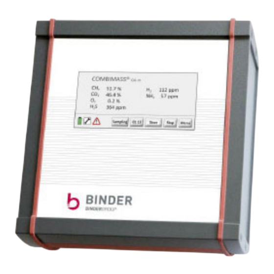
- Page 1 COMBIMASS® Operating Manual COMBIMASS® GA-m Portable gas analyzer Doc. no.: 15128 Edition May 2019...
- Page 2 IMPRINT BINDER GmbH Buchbrunnenweg 18 89081 Ulm, Germany Tel.: +49 731 189 98-0 +49 731 189 98-88 info@bindergroup.info www.bindergroup.info Translation of the original operating manual Produced by: Own production...
-
Page 3: Table Of Contents
Table of contents COMBIMASS® Table of contents Table of contents............i 1 Identification . - Page 4 COMBIMASS® Table of contents 6 Operator control elements ..........35 6.1 Touch-screen display .
- Page 5 Table of contents COMBIMASS® 9.4.4.2 Date / Time............65 9.4.5 Service .
- Page 6 COMBIMASS® Table of contents...
-
Page 7: Identification
Copyright © BINDER GmbH All rights reserved. All rights to this manual and its annexes are of BINDER GmbH. The documents are provided to the recipient for personal use only. Copying, reprinting (electronic or mechanical), translations into other languages and all other reproduction of this manual or parts thereof are permitted only with... - Page 8 Section 1 - Identification COMBIMASS®...
-
Page 9: Notes About This Operating Manual
Should you have any questions to which you cannot find the answers in this operating manual, please contact BINDER. Location of the operating manual This operating manual can assist you only if it is available at all times. You should therefore keep it with the product at all times. -
Page 10: Abbreviations
Section 2 - Notes about this operating manual BINDER Abbreviations Alternating current Bürgerliches Gesetzbuch (German Civil Code) Communauté Européenne (European Community) Direct current DVGW Deutscher Verein des Gas- und Wasserfaches (German Gas and Water Industry As- sociation) European Union Electrostatic sensitive device... -
Page 11: Warnings
BINDER Section 2 - Notes about this operating manual Warnings The safety information warns the user of risks and informs about how these risks can be avoided. Safety information is located at the beginning of each section and before instructions that could result in a dangerous situation. - Page 12 Section 2 - Notes about this operating manual BINDER...
-
Page 13: Product Description
COMBIMASS® Section 3 - Product description Product description Intended use ® The COMBIMASS GA-m gas analyzer has been developed for gas analysis in mobile operation. The device is not suitable for use in a potentially explosive area (EX area). The product must be used only for the following purposes: Qualitative process analysis of biogas, digester gas, landfill gas and synthesis gas ... -
Page 14: Analyzed Gases
Section 3 - Product description COMBIMASS® Analyzed gases Depending on the equipment, the gas analyzer is intended for the analysis of various gases. In the following table you will find the properties of the analyzed gases. NOTE: The actual gases measured can be seen on the start page of the user interface (see È... -
Page 15: Nameplate
COMBIMASS® Section 3 - Product description Nameplate Designation Product name Product code Product group IP protection class according to DIN EN 60529 Product labeling - Recycling and RoHS CE marking Serial number / Year of manufacture Electrical characteristics NOTE The nameplate is not acetone-resistant Do not use cleaning agents containing acetone. - Page 16 Section 3 - Product description COMBIMASS®...
-
Page 17: Technical Data
COMBIMASS® Section 3.4 - Technical data Technical data Dimensions and weight Height: 190 mm Width: 180 mm Depth: 58 mm Weight: 1.7 kg Ambient conditions Protection class: IP66 Ambient temperature: -10 °C to 45 °C Measuring gas Temperature 5 °C to 40 °C Rel. - Page 18 Section 3.4 - Technical data COMBIMASS® Maximum pressure – medium 30 mbar rel. Pressure range – environment 200–1250 mbar abs. Gas flow 400 ml / min (in measurement operation): Interfaces Hose connections: Outside dia. 6 mm / inside dia. 4 mm Gas connections: Gas inlet, gas outlet Data exchange:...
-
Page 19: Measuring Ranges And Measuring Accuracies
COMBIMASS® Section 3.5 - Measuring ranges and measuring accuracies Measuring ranges and measuring accuracies Measuring Typical T time / Typical accuracy range Typical measuring time 0–70 %: +/- 0.5 Vol.-% 0–100 % vol. 50 s / 120 s 70–100 %: +/- 1.5 0.5 Vol.-% 0–60%: +/- 0.5 Vol.-% 0–100 % vol. - Page 20 Section 3.5 - Measuring ranges and measuring accuracies COMBIMASS®...
-
Page 21: Safety
BINDER Section 4 - Safety Safety This section provides information about the safe use of the product described here. All persons authorised to operate, maintain and repair the product must read section “Safety”. WARNING Incorrect use is prohibited! The product must be used only for the purposes described in section “Intended use”. -
Page 22: List Of Safety Symbols Used
Section 4 - Safety BINDER List of safety symbols used Pressurised line This symbol warns about danger through pressure. Risk of explosion This symbol warns about a risk of explosion. ESD – damage through electrostatic discharge This symbol warns about danger through electrostatic discharge. -
Page 23: Electrostatic Sensitive Devices (Esd)
BINDER Section 4 - Safety Electrostatic sensitive devices (ESD) Many electronic devices are inherently sensitive to overvoltages and hence also to electrostatic discharges. The customary international designation for such devices is ESD (electrostatic sensitive device). Applied to cabinets, racks or packaging, the symbol in the following note indicates the use of elec- trostatic sensitive devices and therefore to the touch sensitivity of the respective assemblies. - Page 24 Section 4 - Safety BINDER...
-
Page 25: Safety And Warning Instructions
► Never connect the gas connections to a gas supply with more than +30 mbar above atmospheric pressure. Always use a suitable pressure controller. ► After commissioning, check all gas-carrying parts for leaks. ► Use only original BINDER spare parts and accessories. È For further information, see Section 8.6 "Commissioning"... - Page 26 Section 4.4 - Safety and warning instructions COMBIMASS® WARNING Observe ambient conditions Use of the analyzer in the following environments is prohibited: Corrosive environments In unventilated ducts At temperatures outside a range of -10 °C to +45 °C ...
- Page 27 COMBIMASS® Section 4.4 - Safety and warning instructions WARNING Remove condensation from gas hoses! If the gas to be analyzed is too wet, condensation may collect in the gas hoses. Condensation may contain aggressive and toxic gas residues (e.g., H2S or NH3). The liquid may cause damage to health, the environment or the device.
- Page 28 Use only original spare and wear parts. È For further information, see Section “Maintenance” Observe all fault messages. Maintenance work must be carried out only by Binder or by Binder-trained specialists. Otherwise the availability and accu- racy of the readings cannot be guaranteed.
-
Page 29: Warning Signs On The Device
COMBIMASS® Section 4.5 - Warning signs on the device Warning signs on the device Safe use is possible only when all information required for safe operation is observed. This infor- mation includes, in particular, all safety and warning instructions. ► Replace any missing or damaged signs. - Page 30 Section 4.5 - Warning signs on the device COMBIMASS®...
-
Page 31: Design And Function
COMBIMASS® Section 5 - Design and function Design and function Components of the analyzer system Fig. 5 - 1 Overview of the analyzer system components Designation Explanation The analyzer housing contains the components for gas analysis and Gas analyzer the electronics for monitoring the gas modules, pumps, and valves. Further information at È... -
Page 32: The Combimass Gas Analyzer
Section 5 - Design and function COMBIMASS® Designation Explanation Used to charge the analyzer battery and to transfer saved meas- USB charging ured data to a PC. cable / cable for È “7.5 "Charging the battery". data exchange È “7.6 "Saving and evaluating measured data (data logger)". Used to charge the analyzer battery. - Page 33 COMBIMASS® Section 5 - Design and function Designation Explanation Used to charge the analyzer battery and to transfer saved meas- ured data to a PC. Micro USB port* È “7.5 "Charging the battery". È “7.6 "Saving and evaluating measured data (data logger)". Modbus port* ...
-
Page 34: Functional Description
Section 5 - Design and function COMBIMASS® Functional description 5.2.1 Function sequence – gas analysis After launching the measuring process, the measurement starts automatically. The following steps take place during the measurement: Gas sampling: The gas flow to be measured is sampled from the process gas pipe at the measuring point. -
Page 35: Operator Control Elements
COMBIMASS® Section 6 - Operator control elements Operator control elements Touch-screen display Fig. 6 - 1 Touch-screen display The device is equipped with a touch screen. This is operated by touching the screen with your finger. Further information È 9.1 "Navigating in the menu". NOTE Protect display from soiling and damage Mechanical damage of the touch screen is not included in the warranty. -
Page 36: On/Off Pushbutton
Section 6 - Operator control elements COMBIMASS® On/Off pushbutton The On/Off pushbutton is located on the side of the housing. Press and hold the pushbutton for 1 second to switch on the device. On / Off Fig. 6 - 2 On/Off pushbutton Pushbutton (red) Function... -
Page 37: Quick Guide
COMBIMASS® Section 7 - Quick guide Quick guide Connecting gas hoses WARNING Connection only with pressure reducer and Inline Adsorber! Excessive gas pressure may cause irreparable damage to the device. ► Always use a pressure reducer with 30-mbar outlet pressure that is suitable for the gas ►... - Page 38 Section 7 - Quick guide COMBIMASS® Designation Explanation Cleans the sampling gas. Separates solid or liquid particles Inline adsorber from the sampling gas. Subject to wear (further information at È “10 "Maintenance and servicing"). CAUTION Flammable gases / Risk of poisoning through escaping gases Gases exiting the exhaust hose may be flammable or toxic.
-
Page 39: Switching On The Device And Starting The Measurement
COMBIMASS® Section 7 - Quick guide Switching on the device and starting the measurement Press and hold the red On/Off button (see È 5.1.1 "The COMBIMASS gas analyzer") for at least 1 second to switch on the device. The start page of the user interface appears on the display. Button/indication Function Measure / Stop... -
Page 40: Purging The Analyzer With Air
Section 7 - Quick guide COMBIMASS® Purging the analyzer with air After a measurement, there may be gas residues in the analyzer. These gas residues must be purged with fresh ambient air from the device after each measurement to ensure the highest pos- sible measurement accuracy and lifetime of the measuring cells. - Page 41 COMBIMASS® Section 7 - Quick guide 7.3.1 Table - Purging times Use the times in the table for purging the gas measuring cells. Purging time Measuring time x 1,5 Measuring time x 1,5 - 2 S - 0-50 ppm 10 min. S - 0-500 ppm 15 min.
-
Page 42: Stopping The Measurement And Switching Off The Device
Section 7 - Quick guide COMBIMASS® Stopping the measurement and switching off the device Proceed as follows to stop and switch off the device: When a measurement is in progress, touch [Stop]. Purge the device as described in È 7.3 "Purging the analyzer with air". Switch off the device at the red main switch ... -
Page 43: Charging The Battery
COMBIMASS® Section 7 - Quick guide Charging the battery The battery charge level is shown at the bottom left of the display. When the battery is fully charged, the battery icon is highlighted in green. When the battery needs charging, the battery icon is highlighted in red. -
Page 44: Saving And Evaluating Measured Data (Data Logger)
Section 7 - Quick guide COMBIMASS® Saving and evaluating measured data (option) Depending on the configuration, measured data are stored in the menu 9.4.3 "Data Logging" on the device. For evaluation and archiving, the data can be transferred from the device with a USB cable. Recording data: In menu È... - Page 45 COMBIMASS® Section 7 - Quick guide Settings in the text conversion wizard Step 1: On the first page, you do not need to make any settings. Click [Next] (1). Step 2: Select the comma as separator character (1) and click [Next]. Step 3: Select [More...] (1).
-
Page 46: Evaluating Measured Data
Section 7 - Quick guide COMBIMASS® 7.6.2 Evaluating measured data A maximum of 600 records can be saved. The following information is stored in the .csv file: Sequential No. of the measurement Date and time Measurement location Readings ... -
Page 47: Calibrating The Device
COMBIMASS® Section 7 - Quick guide Calibrating the device The device can be calibrated with test gas. Test gas is a gas mixture with a defined composition. It is used for the following purposes: To compare the current readings of the gas modules with the known composition ... - Page 48 Section 7 - Quick guide COMBIMASS® Press „Calibration Offset“ (1). The "Calibration Offset" is used to compensate the wear of the measuring cell. Over time, the measured value displayed on the start screen decreases. For example, if you enter 0.2 as the offset, 0.2 % will be added to the actual reading.
- Page 49 COMBIMASS® Section 7 - Quick guide The offset just entered is now shown on the [Input Concentration] button. Press [Start Cali- bration] (3) to start the calibration process. The calibration process starts and the noise of the pump can be heard. The following mes- sage is displayed for the duration of the calibration: If the calibration process has been successfully completed, the following message appears on the display:...
- Page 50 Section 7 - Quick guide COMBIMASS®...
-
Page 51: Transport And Commissioning
COMBIMASS® Section 8.1 - Transport Transport and commissioning Transport NOTE Transport the device only in the original bag or in the original case Each analyzer is supplied in a transport case or bag that protects the high- precision electronics from damage. ►... -
Page 52: Transport Of Lithium-Ion Batteries In Airplanes
Section 8.2 - Inspecting received goods COMBIMASS® 8.1.2 Transport of lithium-ion batteries in airplanes There are detailed regulations for lithium batteries in passenger baggage. Normally, our gas anal- ysers can be transported in hand luggage as well as in checked baggage, as the batteries are integrated in the device. -
Page 53: Complaints
COMBIMASS® Section 8.3 - Complaints Complaints Please return any damaged or incorrectly supplied systems to the following address: BINDER GmbH Buchbrunnenweg 18 89081 Ulm, Germany Tel.: +49 731 189 98-0 +49 731 189 98-88 NOTE Returns only with decontamination certificate If the device has been in operation, we can only accept your return with a completed decontamination certificate. -
Page 54: Storage
Section 8.4 - Storage COMBIMASS® Storage To keep an unused device operational for a longer period, observe the following points: The storage location must be cool and dry. Temperature at storage location NOT below - 20°. Too low temperatures can damage elec- ... -
Page 55: Information On Using The Gas Hoses
COMBIMASS® Section 8.6 - Commissioning 8.6.1 Information on using the gas hoses NOTE Recommended plastic hoses We recommend the use of biogas-resistant hoses from Saint Gobain with the following specification: Model: Tygon E-3603 Outer diameter: 6 mm Inner diameter: 4 mm All connectors supplied by us fit to this hose. -
Page 56: Disposal
The directive provides the framework for an EU-wide take-back and recycling of waste equipment. To return your old equipment, please use the return and collection systems available to you. You can return the device to your dealer or Binder GmbH after use. -
Page 57: Menu Settings
COMBIMASS® Section 8 - Menu settings Menu settings NOTE Menu may differ Depending on the software version, the order of the menus or selectable parameters may differ from the description in this manual. Navigating in the menu To operate a function, touch it on the touch screen. Button/indication Function ◄... -
Page 58: Menu Structure
Section 8 - Menu settings COMBIMASS® Menu structure È Start page - see page 59 È Store - see page 60 È Menu - see page 60 È Info - see page 60 È Alert - see page 62 È Data Logging - see page 63 È... -
Page 59: Start Page
COMBIMASS® Section 8 - Menu settings Start page After switching on (see È 7.2 "Switching on the device and starting the measurement"), the main win- dow of the user interface appears on the display. The main window shows the current readings. The lower screen section contains the control buttons and information about the operating state of the analyzer station. -
Page 60: Store
Section 8 - Menu settings COMBIMASS® 9.3.1 Store Touch the [Store] button on the start page to open the menu È 9.4.3 "Data Logging". In this menu, you can define how the measured data are stored on the device. Menu Touch the [Menu] button on the start page (see 9.3 "Start page") to return to the main menu of the user interface. -
Page 61: Info
COMBIMASS® Section 8 - Menu settings 9.4.1 Info Touch the [Info] button to open the Info page. The Info screen contains information about the current software version and the serial number of the device. -
Page 62: Alert
Section 8 - Menu settings COMBIMASS® 9.4.2 Alert The Alert screen lists all current fault states of the device. Button/ Function indication Indicates whether a general alarm (common alarm) is pending. No Device alarm = „No Faults“ Gases Indicates whether an alarm is pending for the corresponding gas cell. (CH4, CO2, ...) -
Page 63: Data Logging
COMBIMASS® Section 8 - Menu settings 9.4.3 Data Logging The measured data are stored on the device in relation to the measurement location. Optionally the re-corded data can be evaluated on the PC. Touch [Delete] to delete all stored measured data. Touch [Locations] to open the Settings menu for saving the measured data. -
Page 64: Adjust
Section 8 - Menu settings COMBIMASS® 9.4.4 Adjust In this menu, you can set the system language and system time for the device. Touch [Language] or [Date] to open the corresponding submenu. È 9.4.4.1 "Language" È 9.4.4.2 "Date / Time" Touch the [⌂... -
Page 65: Date / Time
COMBIMASS® Section 8 - Menu settings 9.4.4.2 Date / Time Enter the system time for the device. Enter the time and date. Touch the [⌂ Home] button to return to the start page. -
Page 66: Service
Section 8 - Menu settings COMBIMASS® 9.4.5 Service This menu is used to calibrate the device with test gas. Proceed as described in È 7.7 "Calibrating the device" to calibrate the device. NOTE: Readings and measured gases are examples only. Depending on the customer’s spec- ifications, the number and type of gases can vary. -
Page 67: Maintenance And Servicing
COMBIMASS® Section 9 - Maintenance and servicing Maintenance and servicing The functioning of the individual components depends to a large extent on the quality of cleaning and maintenance. WARNING Maintenance only by qualified personnel Persons entrusted with maintenance tasks must carefully observe the safety instructions in the operating manual and follow the applicable occupational safety rules. -
Page 68: Replacing The Inline Adsorber
Use without an adsorber may cause damage to the device. If no Inline Adsorber is used, the integrated filter may clog. The internal filter can only be replaced by the customer service of Binder GmbH. Spent Proceed as follows to replace the adsorber. -
Page 69: Spare And Wear Parts
COMBIMASS® Section 10 - Spare and wear parts Spare and wear parts Recommended Art. No.: Quantity Designation Replacement Cycle Depending on 0300858 Inline adsorber - Infiltec, type: DIA-MNI discoloration* *When the adsorber is spent, the color of the gel balls inside changes from orange to clear. Replace the adsorber immediately (see È... - Page 70 Section 10 - Spare and wear parts COMBIMASS®...
-
Page 71: Appendix - Decontamination Certificate
(of the article(s) sent in). I also understand that this certificate does not affect our obligation to hand over a decontaminated pro- duct to BINDER GmbH for repairs. Failure to comply with this rule can lead to claims for compensation. - Page 72 Section 11 - Appendix – Decontamination certificate BINDER...
-
Page 73: Appendix - Usb Charger
COMBIMASS® Section 12 - Appendix – USB Charger Appendix – USB Charger... - Page 74 Section 12 - Appendix – USB Charger COMBIMASS®...
-
Page 75: Index
Index COMBIMASS® Index Abbreviations ......10 Maintenance ......67 Address . - Page 76 COMBIMASS® Index Wrong delivery 53...
- Page 78 BINDER GmbH Buchbrunnenweg 18 89081 Ulm, Germany Tel.: +49 731 189 98-0 +49 731 189 98-88 info@bindergroup.info www.bindergroup.info Translation of the original operating manual Produced by: Own production...
Need help?
Do you have a question about the COMBIMASS GA-m and is the answer not in the manual?
Questions and answers