
Related Manuals for Nexo nanoNXAMP4


Summary of Contents for Nexo nanoNXAMP4
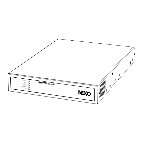
- Page 1 DP7725-01-JC ηNXAMP4 / ηNXAMP4-D POWERED TD CONTROLLER AND NANORM POE REMOTE CONTROL DEVICES USER MANUAL (FIRMWARE V1.6.5)
-
Page 2: Table Of Contents
E: ANALOG INPUTS ................................16 F: POWER AMPLIFIER OUTPUTS ............................. 17 G: MAINS CONNECTORS ..............................18 H: DANTE INTERFACE (NANONXAMP4-D ONLY) ......................18 NANONXAMP4 SUPPORTED SETUPS LIST ..................... 19 NANONXAMP4 DSP BLOCK DIAGRAM ..................... 21 REMOTE CONTROL SOFTWARE DESCRIPTION ..................23 NANONXAMP4 START-UP ........................... - Page 3 TECHNICAL SPECIFICATIONS NANONXAMP4 & NANONXAMP4-D ............61 TECHNICAL SPECIFICATIONS NANORM ....................62 THERMAL DISSIPATION AND CURRENT DRAWN ................... 63 NANONXAMP4 (PINK NOISE, 100 V/50 HZ MAINS) ......................63 NANONXAMP4 (PINK NOISE, 120 V/60 HZ MAINS) ......................63 NANONXAMP4 (PINK NOISE, 230 V/50 HZ MAINS) ......................64 DRAWINGS AND DIMENSIONS ........................
-
Page 4: Safety Precautions
Please check the NEXO Web site nexo-sa.com to get the most up-to-date version of this manual. Ensure you are aware of the safety rules applying to rigging, stacking, or installing on tripod or speaker stand. -
Page 5: Precautions
If the power cord or plug becomes frayed or damaged, or if there is a sudden loss of sound during use of the device, or any unusual smells or smoke should appear to be caused by it, immediately turn off the power switch, disconnect the electric plug from the outlet, and have the device inspected by qualified NEXO service personnel. -
Page 6: Connections
Remove the power plug from the AC outlet when cleaning the device. The performance of components with moving contacts, such as switches, volume controls, and connectors, deteriorates over time. Consult qualified NEXO service personnel about replacing deflective components. HANDLING CAUTION When turning on the AC power in your audio system, always turn on the device LAST, to avoid speaker damage. -
Page 7: Compliance Information
If these corrective measures do not produce satisfactory results, please contact the local retailer authorized to distribute this type of product. If you cannot locate the appropriate retailer, please contact the After Sales department of NEXO-SA, Parc d’Activité du Pré de la Dame Jeanne, B.P.5, 60128 PLAILLY, FRANCE. NANONXAMP4 USER MANUAL... -
Page 8: Doc
EN 55032:2015 + AC:2016 + All:2020 + Al:2020 EN 55035:2017 + AC:2019-11+ All:2020 EN 55103-2:2009 EN 61000-3-2:2014 EN 61000-3-3:2013 + A1:2019 Restricted substances in electrical products EN IEC 63000:2018 Plailly, April 1 , 2024 Joseph CARCOPINO, R&D Director PAGE 8 / 68 NANONXAMP4 USER MANUAL... -
Page 9: Informaton
Open the box with care to prevent damage on the content. Inside you will find: • 1 x nanoNXAMP4 or nanoNXAMP4-D Powered TDController. • 1 x nanoNXAMP4 / nanoNXAMP4-D Quick Start guide • 2x Euroblock type Input connector • 2x Euroblock type Output connector •... -
Page 10: Introduction
NEXO speakers. A TD Controller is a highly sophisticated audio processing unit, design to enhance the sonic performances as well as to protect the NEXO speakers. This processor is coupled with four channels of power amplifier. RACK INSTALLATION... -
Page 11: Speaker Cable Choice
Air flow of the nanoNXAMP4 or nanoNXAMP4-D is from side to back, thus installation can mix DTDAMP (with DTD Controller), first generation NXAMP or NXAMPmk2 in the same rack, all using the same air flow direction. SPEAKER CABLE CHOICE WARNING! High voltage can be present on the power amplifier output terminals. -
Page 12: Front Panel Description
Green: The nanoNXAMP4 or nanoNXAMP4-D is operational. • Pulse Green: The nanoNXAMP4 or nanoNXAMP4-D is in Standby mode. • Amber: The nanoNXAMP4 or nanoNXAMP4-D is triggered in Standby mode through the GPIO. INPUT INDICATOR There are three possible states for this led: •... -
Page 13: Back Panel Description
(US form factor). See further in the manuel how to setup those external remote controls. B: GPIO PORT The GPIO port is used to interface the nanoNXAMP4 to external remote control or monitoring device, or to do some simple tasks like 12 Volts triggering, muting, going to stand-by mode or controlling the volume. - Page 14 The below diagram shows a potentiometer connection for the remote volume control via GPIO. Note that Pin 4 to Pin 7 are available for volume control (see GPIO Settings Menu further in the manual). Potentiometer Connect iper to Pin , , or . PAGE 14 / 68 NANONXAMP4 USER MANUAL...
-
Page 15: C: Air Exhaust
C: AIR EXHAUST Do not obstruct the air exhaust at the back of the nanoNXAMP4 and leave at least 80 mm behind the unit for air flow. The air intakes are on both sides of the unit therefore a 25 mm clearance is needed on at least one of the two side of the unit. -
Page 16: D: S/Pdif Interface
D: S/PDIF INTERFACE The nanoNXAMP4 features a S/PDIF Input and Output interface on RCA Phono sockets that can be used to connect to digital audio sources (like TV receiver or network streamer) or output some of the nanoNXAMP4 Analog Inputs, Input Mix or Area Mix to other devices (like other nanoNXAMP4 units in daisy chain). -
Page 17: F: Power Amplifier Outputs
F: POWER AMPLIFIER OUTPUTS There are four power amplifier outputs on the nanoNXAMP4, bridgeable (Bridge Tile Load : BTL) two by two to increase the power on the resulting output. WARNING! The exclamation point printed next to the output terminals of the amplifier is, in addition to the CLASS 2 WIRING test, intended to alert users to the risk of hazardous voltages. -
Page 18: G: Mains Connectors
Connecting cables to the supplied female output connector is illustrated below. G: MAINS CONNECTORS The nanoNXAMP4 can accept Mains from 100 to 240 Volts, both 50 to 60 Hz, thanks to its high efficiency active PFC (Power Factor Correction) system. -
Page 19: Nanonxamp4 Supported Setups List
NANONXAMP SUPPORTED SETUPS LIST The below list shows the NEXO cabinet supported by this version of the firmware (v1.6.5). Please go to nexo-sa.com to check for firmware updates to enable support for new cabinets. NANONXAMP4 USER MANUAL PAGE 19 / 68... - Page 20 PAGE 20 / 68 NANONXAMP4 USER MANUAL...
-
Page 21: Nanonxamp4 Dsp Block Diagram
Output Block: These four outputs are related to the power amplifier modules and the DSP processing for the selected NEXO speaker. A Area output should be routed to each Output. In case of bridge (BTL) setup, two outputs (A+B or C+D) are used together as a pair to feed one speaker. - Page 22 PAGE 22 / 68 NANONXAMP4 USER MANUAL...
-
Page 23: Remote Control Software Description
REMOTE CONTROL SOFT ARE DESCRIPTION NANONXAMP4 START-UP The nanoNXAMP4 startup is straightforward. Once all the wiring has been done and mains is present, the front panel STATUS LED is light up and the device is ready to be configured. To do so you must access the embedded webpage through the network port of through the Wi-Fi connection (default mode for nanoNXAMP4 Wi-Fi connection being Access Point mode). -
Page 24: Wired Network Control Connection
2. Input: Allow to adjust input related parameters like level, gain, phase inversion, sensitivity (for Analog Inputs) and setup inputs mixes. 3. Area: The heart of the nanoNXAMP4 where the input (or inputs mixes) can be routed with priority input and compressor settings. -
Page 25: Dashboard Page Description
MONO / STEREO button. 3. Dante: Four Dante inputs are available only on the nanoNXAMP4-D through the dedicated network port marked with the Dante logo. An input level meter allows to check signal presence, and the Gain/Trim function allows to adjust the input gain from -15 dB to +15 dB in 0.1 dB steps. -
Page 26: Area Page Description
(clicking the Mono/Stereo button) and output volume is adjustable between mute and 0 dB in 0.1 dB steps. Click on the speaker logo to toggle the mute function for a specific Area. The Area page is divided into four sections: PAGE 26 / 68 NANONXAMP4 USER MANUAL... - Page 27 Priority Input is above the adjustable Threshold (eventually overriding the Area Volume by a new setting), “Duc ing” will reduce the level of the Primary Input when Priority Input is above the adjustable Threshold. NANONXAMP4 USER MANUAL PAGE 27 / 68...
- Page 28 2. Volume: This page allows to adjust the minimum and maximum volume that can be reached through the GPIO control of through the external NANORM volume controller (see further in the manual for detailed specs). GPIO volume control is setup from this page as well. PAGE 28 / 68 NANONXAMP4 USER MANUAL...
- Page 29 3. Restrictions: Select which input is allowed to be routed on this specific area. Useful to limit the input list available from the NANORM volume controller. Primary Input and Priority Input cannot be restricted. Move the switch to “Allowed” or “Restricted” to change the source status. NANONXAMP4 USER MANUAL PAGE 29 / 68...
-
Page 30: Output Page Description
4. Compressor: This page allows to tune the output compressor of each Area. This compressor can be setup by the user and does not override the protection of the NEXO Speaker Setup. In “Default” mode only the Threshold is ad ustable, the “Manual” mode gives access to every parameter of the compressor. - Page 31 Delay can be entered in Samples, Ms, Feet or Meter with a maximum of 4800 samples / 100 ms / 112.50 feet / 34,3 meters. NANONXAMP4 USER MANUAL PAGE 31 / 68...
- Page 32 15 different EQ type can be selected (Low/High shelves with 6 dB, 12 dB slopes or adjustable Q, Low/High pass with 6 or 12 dB slopes, First and Second order All-pass, Parametric, Band-pass and Notch). PAGE 32 / 68 NANONXAMP4 USER MANUAL...
- Page 33 4. Speaker Preset: This page controls the selection of a NEXO Speaker Preset to be attached to the selected amplifier output. The Preset must be selected from the Spea er Library (Clic on the “Select Preset from library” button). Regularly chec for nanoNXAMP firmware updates from our website to add new or updated Speaker Preset.
-
Page 34: Settings Page Description
1. System Information: This page regroups some editable text field useful to identify the device, such as Device Name, Venue Name, Customer Name, Asset Tag Number, Installer Name with contact info, Date of installation and Installation Notes. PAGE 34 / 68 NANONXAMP4 USER MANUAL... - Page 35 2. Device: Here can be found information about the nanoNXAMP4 or nanoNXAMP4-D such as Serial number, Firmware version and mac addresses (both LAN and Wi-Fi), except the mac address for the Dante network port than can be read back from the Dante Controller software.
- Page 36 (connected through the LAN port of through the Wi-Fi) will be listed here. Manual addition using IP address can be used as well. Click on the “Pair” button to pair a NANORM remote control device to the nanoNXAMP4 or nanoNXAMP4-D. Once paired you can select which Area of the amplifier will be remote controlled by the NANORM.
- Page 37 4. Backup and Restore: The settings of the nanoNXAMP4 can be backup and restore from this page by clicking the proper button. Restarting the unit or reset it is available as well. 5. Speaker Library: The list of the embedded presets for NEXO Speakers can be displayed here.
- Page 38 6. Security: Access to the unit can be password protected by switching the “Password Protection” to Enabled and entering a password twice. PAGE 38 / 68 NANONXAMP4 USER MANUAL...
- Page 39 In that case, please reboot the unit to have access to the remote control before the amplifier goes to stand-by again or reset the unit. Mute time and Stand-by time can be selected from OFF to respectively 10 and 60 minutes. NANONXAMP4 USER MANUAL PAGE 39 / 68...
- Page 40 8. Output Routing: This page controls the audio routing from the nanoNXAMP4 to the digital output of the devices (2 channels on the SPDIF output for both models and 4 channels of Dante on the nanoNXAMP4-D only). For each digital output the source can be chosen among the analog inputs, the SPDIF input, the Dante input, the Mix output (mix of input sources, see Input Page Description) or the Area output (see Area Page Description).
- Page 41 9. Dante: The Dante page displays basic information about the Dante module like clocking status, mac and IP address, firmware revision and AES67 mode. NANONXAMP4 USER MANUAL PAGE 41 / 68...
- Page 42 10. GPIO: This page controls the functions linked to every GPIO Pins. The explanation is directly written on the control page. See Back Panel Description above in the manual for hardware description of the GPIOs of the nanoNXAMP4 and nanoNXMAP4-D. PAGE 42 / 68...
- Page 43 11. LAN: Controls the IP settings of the LAN interface. DHCP and Static addressing are available. On top of IP address, Network mask, Gateway and two DNS servers’ addresses can be entered for more complex networks integration. NANONXAMP4 USER MANUAL PAGE 43 / 68...
- Page 44 Note that Wi-Fi mode can be “Access Point” for direct connection from client (default mode) of as a client to join an already existing Wi-Fi infrastructure (SSID and password should be provided then). PAGE 44 / 68 NANONXAMP4 USER MANUAL...
-
Page 45: Nanorm Poe Remote Control Devices
Each NANORM device can control one Area only but that one Area can be routed to several or all the nanoNXAMP4 output and routed through SPIDF or Dante output to other nanoNXAMP4 devices as well (see Settings Page Description > Output routing). On the other hand, the remote control of four Areas would require four NANORM devices, each assigned to one of the 4 individual Area. -
Page 46: Nanorm Connection To Nanonxamp4
NANORM CONNECTION TO NANONXAMP4 The illustration below outlines how to connect multiple NANORM devices to a nanoNXAMP4 amplifier, via the use of a standard PoE network switch and Cat5 cable. S UTP cat. e Cable S UTP cat. e Cables... - Page 47 2. Mount the electrical box into the wall 3. Connect the Ethernet cable to the NANORM unit. 4. Screw the NANORM unit into the electrical box. Put the front panel on and click it into place. NANONXAMP4 USER MANUAL PAGE 47 / 68...
- Page 48 PAGE 48 / 68 NANONXAMP4 USER MANUAL...
-
Page 49: Nanorm Device Operation
Once the Wall-S1 device is receiving power via the connected Ethernet cable, the product will power up and display the NEXO logo for a few seconds. The NEXO logo will disappear and be replaced by the setup screen. The setup screen displays the following: •... - Page 50 2. Step 2: Edit the Device's IP Setting (if required) When the device is connected to a nanoNXAMP4 or nanoNXAMP4-D amplifier via a network router, the NANORM device will be automatically assigned an IP address (dynamic DCHP) - this is the default setting, and in this situation, there is no need to edit the IP settings.
- Page 51 Step 5 to ensure each device has a unique IP address. 11) Twist the rotary encoder one click to the right (clockwise) and tap the rotary encoder to confirm the selection of the option labelled "Address". NANONXAMP4 USER MANUAL PAGE 51 / 68...
- Page 52 17) You will be presented with the question "Apply IP Changes?" 18) Twist the rotary encoder one click to the left (anticlockwise) and tap the rotary encoder to confirm the selection of the option labelled "Yes". PAGE 52 / 68 NANONXAMP4 USER MANUAL...
- Page 53 3. Step 3: Connect to the nanoNXAMP4 using the Control webpage. If you haven't already, connect now to the nanoNXAMP4 or nanoNXAMP4-D amplifier via your phone, tablet or computer using the Control webpage. Refer to the Remote-Control Software Description above in the manual to do so.
- Page 54 IMPORTANT - If accessing the Control webpage by connecting to the nanoNXAMP4 via a wired (Ethernet) network connection, we strongly recommend changing the WIFI settings as outlined below. • Under the 'Settings Menu', go to 'WIFI' settings and select the option "Disable WIFI" when LAN connected.
- Page 55 "ONLINE" icon will be displayed alongside it. 5. Step 5: Select the audio Area the device is intended to control. In the nanoNXAMP4 control webpage, click on the device shown within the paired devices menu and navigate to the tab labelled "General".
- Page 56 Area it is associated with. Individual NANORM device identification can be established by selecting the Find Me option in the 'Settings'> 'External Devices' in the nanoNXAMP4 or nanoNXAMP4-D control webpage. The display and rotary encoder illumination of the connected device will flash.
-
Page 57: Nanorm Device Setup
NANORM DEVICE SETUP As described above, see the Settings Page Control > External devices to have the list of functions that can be associated with the NANORM device. NANONXAMP4 USER MANUAL PAGE 57 / 68... -
Page 58: Remote Control - Nexo Nemo
See Settings Page Description / LAN for more details. NB: nanoNXAMP4-D has two RJ45 ports, one for remote control and one for Dante connection. Be sure to use the Remote-Control port to connect the unit to the remote-control software. - Page 59 • A configurable way of managing alerts of different levels. • Visualizing and exporting a log of all the values of the NEXO devices (including temperature, voltage, current…) that you can record when NeMo is online. • A fully configurable Live mode.
-
Page 60: Maintenance
Always unplug the nanoNXAMP4 from the main before cleaning it. Regularly check the dust level of the air intakes of the nanoNXAMP4. If some dust is inserted into the cooling tunnel of the amplifier, use compressed air to remove it from the amplifier. -
Page 61: Technical Specifications Nanonxamp4 & Nanonxamp4-D
TECHNICAL SPECIFICATIONS NANONXAMP & NANONXAMP D NANONXAMP4 USER MANUAL PAGE 61 / 68... -
Page 62: Technical Specifications Nanorm
TECHNICAL SPECIFICATIONS NANORM PAGE 62 / 68 NANONXAMP4 USER MANUAL... -
Page 63: Thermal Dissipation And Current Drawn
For these measurements, the test signal is a pink noise with bandwidth limited 22 Hz to 22 kHz, all channels driven. 1 BTU = 1055.06 J = 0.252 kcal. (W) x 860 = cal/h NANONXAMP4 (PINK NOISE, 100 V/50 HZ MAINS) Line Power Watts... -
Page 64: Nanonxamp4 (Pink Noise, 230 V/50 Hz Mains)
NANONXAMP4 (PINK NOISE, 230 V/50 HZ MAINS) Line Power Watts Output/ch Heat Dissipation MODE Current consumption Dissipated Power(W) Volt(V) Btu/h kcal/h Audio (Eco) Audio Audio (Digital) Standby Trigger (Eco) Trigger Network Only Idle 8ohms/ch output 4ohms/ch power 2ohms/ch 8ohms/ch 4ohms/ch... -
Page 65: Weee Information
Entsorgungsinformation für Länder außerhalb der Europäischen Union: Dieses Symbol gilt nur innerhalb der Europäischen Union. Wenn Sie solche Artikel ausrangieren möchten, kontaktieren Sie bitte Ihre örtlichen Behörden oder Ihren Händler und fragen Sie nach der sachgerechten Entsorgungsmethode. (weee_eu_de_02) NANONXAMP4 USER MANUAL PAGE 65 / 68... -
Page 66: Informations Concernant La Collecte Et Le Traitement Des Dechets D'equipements Electriques Et Electroniques
Información sobre la eliminación en otros países fuera de la Unión Europea: Este símbolo solo es válido en la Unión Europea. Si desea desechar estos artículos, póngase en contacto con las autoridades locales o con el vendedor y pregúnteles el método correcto. (weee_eu_es_02) PAGE 66 / 68 NANONXAMP4 USER MANUAL... -
Page 67: User Notes
USER NOTES NANONXAMP4 USER MANUAL PAGE 67 / 68... - Page 68 NEXO S.A. Tel : +33 (0)3 44 99 00 70 Parc d’Activité Fax : +33 (0)3 44 99 00 30 Du Pré de la Dame Jeanne E-mail : info@nexo.fr B.P.5 nexo-sa.com 60128 Plailly FRANCE...
Need help?
Do you have a question about the nanoNXAMP4 and is the answer not in the manual?
Questions and answers