
Subscribe to Our Youtube Channel
Related Manuals for Nexo NXAMPMK2 Series


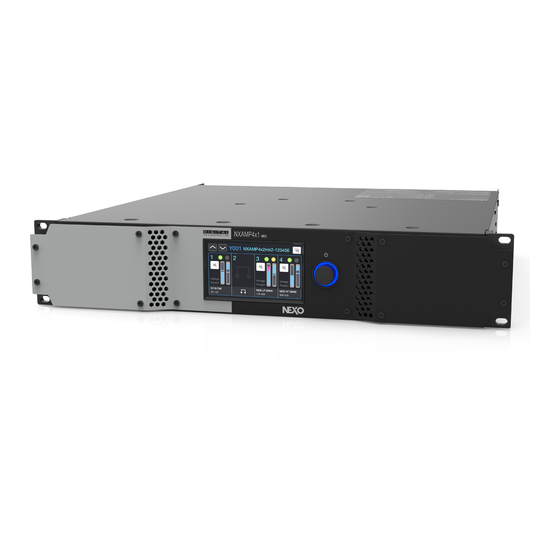
Summary of Contents for Nexo NXAMPMK2 Series
- Page 1 DP4946-02a-DI NXAMPMK2 POWERED TD CONTROLLER NXAMP4x1 NXAMP4x2 NXAMP4x4 USER MANUAL (LOAD5_28)
-
Page 2: Table Of Contents
TABLE OF CONTENTS TABLE OF CONTENTS ..........................2 SAFETY PRECAUTIONS ..........................6 SAFETY INSTRUCTIONS ............................6 PRECAUTIONS................................ 7 POWER SUPPLY/POWER CORD ..............................7 WATER WARNING ..................................7 IF YOU NOTICE ANY ABNORMALITY .............................7 LOCATION.......................................7 CONNECTIONS ....................................8 MAINTENANCE ....................................8 HANDLING CAUTION ..................................8 COMPLIANCE INFORMATION ........................9 FCC INFORMATIONS (U.S.A.) .......................... - Page 3 USE THE AMPLIFIER WITHOUT THE TDCONTROLLER FUNCTIONALITY ................. 25 INPATCH AND OUTPATCH ..........................26 INPUT PATCH ....................................26 INPUT ALIGNMENT ..................................26 DIGITAL AUDIO SOURCE SELECTION (NXAEDT ONLY) ......................27 CHECKING THE OUTPUT PATCH ..............................27 VOLUME ................................27 DELAY ..................................28 GAIN ..................................
- Page 4 LINKING SEVERAL DPU TOGETHER ............................60 REMOTE CONTROL – NEXO NEMO ......................61 IP BASED REMOTE CONTROL PROTOCOL ....................... 61 NEMO (NEXO REMOTE): NXAMPMK2 CONTROL SOFTWARE ................. 61 OTHER REMOTE-CONTROL OPTIONS ....................... 62 FIRMWARE UPDATE – NEXO NEFU ......................63 ACCESSORIES ............................
- Page 5 PINK NOISE, 100V/50HZ MAINS ..............................68 PINK NOISE, 120V/60HZ MAINS ..............................69 PINK NOISE, 230V/50HZ MAINS ..............................69 NXAMP4X2MK2 ..............................70 PINK NOISE, 100V/50HZ MAINS ..............................70 PINK NOISE, 120V/60HZ MAINS ..............................70 PINK NOISE, 230V/50HZ MAINS ..............................71 NXAMP4X4MK2 ..............................71 PINK NOISE, 100V/50HZ MAINS ..............................
-
Page 6: Safety Precautions
Please check the NEXO Web site nexo-sa.com to get the most up-to-date version of this manual. Ensure you are aware of the safety rules applying to rigging, stacking, or installing on tripod or speaker stand. -
Page 7: Precautions
If the power cord or plug becomes frayed or damaged, or if there is a sudden loss of sound during use of the device, or any unusual smells or smoke should appear to be caused by it, immediately turn off the power switch, disconnect the electric plug from the outlet, and have the device inspected by qualified NEXO service personnel. -
Page 8: Connections
Remove the power plug from the AC outlet when cleaning the device. The performance of components with moving contacts, such as switches, volume controls, and connectors, deteriorates over time. Consult qualified NEXO service personnel about replacing deflective components. HANDLING CAUTION When turning on the AC power in your audio system, always turn on the device LAST, to avoid speaker damage. -
Page 9: Compliance Information
If these corrective measures do not produce satisfactory results, please contact the local retailer authorized to distribute this type of product. If you cannot locate the appropriate retailer, please contact the After Sales department of NEXO-SA, Parc d’Activité du Pré de la Dame Jeanne, B.P.5, 60128 PLAILLY, FRANCE. NXAMPMK2 USER MANUAL... -
Page 10: Doc
See www.dtsc.ca.goc/hazardouswaste/perchlorate. (Perchlorate) This applies only to the products distributed in the United States of America. Declaration of Conformity NEXO SA ZA DU PRE DE LA DAME JEANNE 60128 PLAILLY – France Declare under our sole responsibility that the product... -
Page 11: Informaton
INFORMATON European models Purchaser/User information specified in EN55103-2:2009. Conforms to Environments: E1, E2, E3 and E4. The model number, serial number, power requirements, etc., be found on or near the name plate, which is at the top of the unit. You should note this serial number in the space provided below and retain this manual as a permanent record of your purchase to aid identification in the event of theft. -
Page 12: Introduction
A TD Controller is a highly sophisticated audio processing unit, design to enhance the sonic performances as well as to protect the NEXO speakers. This processor is coupled with four channels of power amplifier. RACK INSTALLATION The NXAMPmk2 should be mounted into a suitable rack unit, ensuring both front and rear mounting holes are used to protect the device from mechanical damage. -
Page 13: Front Panel Description
Once all the wiring has been done and mains is present, the surround backlight of the encoder is glowing slowly. Long press this encoder till the system boots up. The first screen will show the NEXO logo and the revision of the firmware starting with “LOAD”. -
Page 14: A: Power Outputs
CH4) depending on speaker presets used and “Output Mode” setting. See Speaker cabling & output mode section precisely describing this process, and also presenting typical speaker cabling cases. In all cases, please check front panel indication to know where to connect your NEXO speaker. Checking the output patch section explains where to find this information. -
Page 15: B: Expansion Slot
B: EXPANSION SLOT Through the expansion slot located in the middle of the back panel of the NXAMPmk2, the default network based remote control card can be replaced by a digital audio input and network remote control card. At the time of writing, AES/EBU, EtherSound , Dante (and AES67) digital audio format are supported through expansion boards (See... -
Page 16: F: Rs-232 Port
F: RS-232 PORT This serial port is used to connect a NEXO DPU (Digital Patching Unit) device. Note that it is not possible to upgrade the NXAMPmk2 firmware though this serial port. The RxD pin is the “Receive data” pin from the NXAMP point of view. Thus, this is an input. The TxD pin is the “Transmit data”... -
Page 17: Audio Input And Output Connections
AUDIO INPUT AND OUTPUT CONNECTIONS Place the NXAMPmk2 in the audio chain just before the NEXO speakers, typically at the output of the mixer or matrix. WARNING! Unplug the device from mains before connecting or disconnecting any cable to it. -
Page 18: Speaker Cabling & Output Mode
As a reminder, NEXO speakers are mostly cabled as following: Subwoofers on 1+/1-, Passive speakers on 2+/2- and Active speakers (2 channels) with LF on 1+/1- and HF on 2+/2-. -
Page 19: Configuration With Two Speakers 1+/1
CONFIGURATION WITH TWO SPEAKERS 1+/1- In that case, we will take two L15 subwoofers (taking the signal from 1+/1-), recalled on amplifier CH1 and CH2. In that configuration, the cabling is straight forward, CH1 is taken from speakON A and CH2 is taken from speakON B. -
Page 20: Conclusion & 4-Channel Arrangement
CONCLUSION & 4-CHANNEL ARRANGEMENT We can summarize the cabling with the following table: Combination SpeakON to be used Output mode Note SUB (1+/1-) SUB (1+/1-) Straight Dynamic Straight PASSIVE (2+/2-) PASSIVE (2+/2-) Static Crossed (deprecated) Both on SUB side SUB (1+/1-) PASSIVE (2+/2-) (use Link or Y adaptor) Both on SUB side... -
Page 21: Amplifier Start-Up & Menu Descriptions
AMPLIFIER START UP & MENU DESCRIPTIONS AMPLIFIER START-UP The NXAMPmk2 setup is straightforward. Once all the wiring has been done and mains is present, the surround backlight of the encoder is glowing slowly meaning that the amplifier is in standby mode. Long press the encoder to leave standby mode until the system boots up. -
Page 22: Header Menu
HEADER MENU When channel settings are displayed, whatever the page, push on the rotary encoder to access the header menu. See capture below. Header menu A: INACTIVE VIEW, LOCK & STANDBY On the top-left corner, three shortcuts are available: Show the inactive view. The Inactive view is a simplified view showing only relevant information that you would need once all the configuration is done. -
Page 23: Reset To Factory Settings
Delay: Edit delay (up to 1 second) on one or several channels at once. Gain: Edit gain (-18 to +18 dB) on one or several channels at once. Array EQs: Two settings of Array-EQ allow for a better compensation of ground, stacking and line-array effect, on Low and High frequencies. -
Page 24: Channel Settings
CHANNEL SETTINGS METERS & SPEAKER PRESET This section lists all the information you can find on the Meters page, and how to change the speaker preset. Speaker preset, the first line shows the Speaker name (here “S11 ”) and the Speaker mode if any (here “Omni”... -
Page 25: Speaker Preset Selection
This menu allows to select either a speaker preset for selected channels (through the “Series”, “Cabinet”, “Mode”, and “Cross-over” button), or four-channel speaker preset arrangement provided by NEXO (through the “NEXO” button). -
Page 26: Inpatch And Outpatch
INPATCH AND OUTPATCH Once the speaker presets have been recalled, and back to the default Meters page screen, press the “Up navigation button” to enter the input patch page. You can also access it from the header menu. INPUT PATCH Select the channel you want to modify the input patch for by pressing the area just above the Speaker Preset Name. -
Page 27: Digital Audio Source Selection (Nxaedt Only)
CHECKING THE OUTPUT PATCH On all channel settings pages, the Speaker Preset Name is blinking alternatively with the output letter and the output pinout (1+/1- or 2+/2- of the NL4 connector). Check that the NEXO Speakers are correctly connected. Send some low-level audio or test signal into the NXAMPmk2 and check that each Speaker or Sub is outputting a non-distorted sound (you might need to check the channel output volume first, see next paragraph). -
Page 28: Delay
DELAY Select a channel (button is highlighted), then turn the wheel to change the delay setting. You can select multiple channels, when a selected channel reaches the maximum value, it will cease to increase by continuing to turn the wheel, but other selected channels may still increase the setting; Be careful not to change a gap between two channel settings when selecting multiple channels at the same time. -
Page 29: Array-Eqs
ARRAY-EQS Select an Array-EQ in a channel (button is highlighted), then turn the wheel to change the Array-EQ setting. You can select multiple channels, when a selected channel reaches the maximum value, it will cease to increase by continuing to turn the wheel, but other selected channels may still increase the setting; Be careful not to change a gap between two channel settings when selecting multiple channels at the same time. -
Page 30: Eq Main View
EQ MAIN VIEW When channel (or multi-channels) has been selected, the EQ main view is displayed: EQ main view Return to previous channel settings EQ page. Copy the EQ curve from selected channel (or multi-channels). Paste the EQ curve previously copied to selected channel (or multi-channels). Switch on/off all the EQ on channel. - Page 31 Type of filter, to select between Bell (Parametric), HighPass (2 Order), LowPass (2 Order), HighShelf (with adjustable Q), LowShelf (with adjustable Q) or Notch, from the following popup. (10) Frequency adjustment, to select among the 120 center frequencies available for each filter from 20 Hz to 20 kHz.
-
Page 32: Internal Menus
INTERNAL MENUS From all channel settings pages, just push on the rotary encoder to access the header menu. This section describes all internal menus and the settings you can adjust there. All other items from header menu have already been described in previous header menu section. -
Page 33: To Save A Scene
TO SAVE A SCENE Prepare all parameters you want to save by adjusting all channel settings (speaker preset, gain, EQ, etc..). In the scenes list, select an empty slot, or a slot you want to overwrite. In this example, we will take the empty slot n°... -
Page 34: Remote Control
The Device ID is always included in front of the Dante™ card name on the Dante™ network. On the following Dante™ Controller screenshot, we can see that the Dante™ card name is “Y 1 -NEXO-NXAMP4x4mk2- ”. The Device ID can be edited on Dante™ Controller by editing it directly in the Dante™ card name. -
Page 35: Name
NAME Here can be modified the NXAMPmk2 name. This name is used and displayed by the remote-control software (NEXO NeMo). NB: The NXAMPmk2 name is not the same than the Dante™ card name, but a function is available in NeMo to sync them on request (see NeMo user guide). -
Page 36: Analog Fallback
ANALOG FALLBACK Analog Fallback is intended to provide analog audio redundancy of the digital audio inputs. It works with both NXDT104mk2 (Dante ) and NXAE104 (AES/EBU). Analog Fallback (and digital audio) still works on NXAMPmk2 with NXDT104 (Dante ) and NXES104 (Ethersound ), even if remote control is reduced to NXAMPmk1 controllable parameters set (cannot control new mk2 functions). -
Page 37: Monitoring
NEXO-NXAMP4x4mk2- ” has subscribed to channel 1, 2, from the Dante device named “NEXO-PC” (a computer running the Dante Virtual Soundcard software). NB: The NXDT104mk2 can subscribe up to four different channels from four different Dante transmitters. The digital audio status for the NXAMPmk2 is declared OK if all digital input channels E/F/G/H are declared OK, otherwise all analog inputs are un-muted. -
Page 38: Monitoring Menu
MONITORING MENU The Monitoring menu, accessible from the header menu, gives access to a large range of NXAMPmk2 monitoring parameters. This section describes each available sub-menu. ALERTS On this screen are displayed all the data stored about Errors, Alarms, Warnings (see Alert List section). -
Page 39: Global Parameters
By clicking on (1), you can select an averaging time (5 min to 1 week) for the measurements. By clicking on (2), you can reset all the data in the Log file after confirming with the following popup. The two arrows in area can be used to navigate between global parameters and per-channel parameters, described below. -
Page 40: System Headroom
SYSTEM HEADROOM The System Headroom menu displays for each channel (selected by the top buttons Ch.1 to Ch.4) the headroom available from both the amplifier channel and the speakers connected to it. On the amplifier headroom monitoring part, two vu-meters with a 60 dB scale are displaying the Output Voltage and the Output Current, both referring to 0 dB being the maximum voltage of the maximum current the amplifier can output. -
Page 41: Monitoring Mode
2 alerts (“High” or “Low” impedance) if the measured impedance is out of the given low/high user-defined range. Here are the parameters that can be configured: MONITORING MODE Here can be modified the Load Monitoring mode. 3 modes are available. OFF: The Load Monitoring is turned off. -
Page 42: Frequency
FREQUENCY Here can be adjusted the frequency at which the impedance measurement will be done for the speaker(s) connected to the channel selected. The frequency is adjustable from 14500 to 21000 Hz in 1/12 octave steps. Most of the time, there is no need to change this frequency if you are using the Internal Generator. If external pilot tone is used (from the audio program sent to the NXAMPmk2 on its analog or digital inputs), be sure that the frequency selected here is close as possible to the pilot tone frequency. -
Page 43: Input Monitoring
INPUT MONITORING The NXAMPmk2 Input Monitoring is an audio input-based pilot tone detection and monitoring function, measuring in real-time the pilot tone presence on the amplifier input channel. This allows to report (through its GPIO port or network) whether the audio sources are correctly connected to the amplifier and ready to use. -
Page 44: Monitoring Mode
Here are the parameters that can be configured: MONITORING MODE Here can be modified the Input Monitoring mode for the selected channel. 2 modes are available. OFF: The Input Monitoring is turned off. The channel input is not monitored, no alerts are raised. ON: The Input Monitoring is turned on. -
Page 45: Settings Menu
SETTINGS MENU The Settings menu, accessible from the Header Menu, gives access to a large range of settings for many of the NXAMPmk2 parameters. This section describes each available sub-menu. REMOTE CONTROL Remote control settings available in this sub menu are the same than the one directly accessible from the header menu (internal menus area). -
Page 46: Screen & Appearance
From the remote-control software NEXO NeMo, it is possible to create groups of devices and zones of channels. They are saved in a document called session. When a session is online, the NXAMPmk2s are aware of the groups and zones they belong to. -
Page 47: Lock & Sleep
This menu allows you to set the password for the amplifier lock function and manage the screen saver. Password is used to lock the screen, the remote-control access (NEXO NeMo or third-party controllers) and the firmware update (NEXO NeFu). Using a password in not mandatory and can be left empty. -
Page 48: Input Pins Configuration
INPUT PINS CONFIGURATION In Custom Mode, to configure the input pins (control functions), press GPInputs. Then select the desired input pin (numbered from GPI 1 to GPI 5) to open the following popup where all available functions are displayed: Then choose a parameter (see table below, e.g. Switch Scene), then if needed a first and a second option (e.g. -
Page 49: Output Pins Configuration
OUTPUT PINS CONFIGURATION In Custom Mode, to configure the output pins (monitoring functions), press GPOutputs. Outputs pins are numbered from GPO 1 to GPO 8. To configure an output pin, follow the same steps as above for the input pins. Possible States Name Options... -
Page 50: Delay Unit
Possible States Name Options Description High Imp. Load Monitoring is reporting fault (high or low Load Mon. Alert Channel load) on selected channel. Load Monitoring is reporting fault (high or low Load Mon. Alert (global) load) on selected channel. All channel amplifiers are ok, i.e. no channel is Amplifier Status reporting a fault. -
Page 51: Energy Saver Enabled
ENERGY SAVER ENABLED When enabled, the amplifier goes to Energy Saver Mode when no input signal has been received during a given time interval. The power consumption is then reduced. When input signal is received again, the amplifier leaves the Energy Save Mode. No-signal time interval can be adjusted from 1 minute to 3 hours. -
Page 52: Alerts List
ALERTS LIST GLOBAL MAINS1 VOLTAGE(V) The mains 1 voltage is out Automatically shut down A. The connection of the limits and reboot. After reboot, between the power source Check AC power Over 276[V] (4x1/4x2) Error Screen displayed and the amplifier might be connection Under 60[V] or over 276[V] until... -
Page 53: Amplifier Muting Output
AMPLIFIER MUTING OUTPUT This alert is triggered only A. Environmental if the alert condition cannot The output is muted to temperature is too high All channel Mute. removed other protect the amplifier B. Unexpectedly protections such as limiter, overloaded mute and fan rotation. FAN1 ERROR Number of malfunctioned fans:... -
Page 54: Per Channel
PER CHANNEL POWER AMP DC OUTPUT ALERT Automatically shut down DC output is detected in The amplifier unit might and reboot. After reboot, given amplifier malfunction due to some Call service center Error Screen displayed until channel unexpected reason. the causes are removed. AMPLIFIER OVERTEMPERATURE LEVEL1 Amplifier temperature reaches 65 degree:... -
Page 55: Low Load Alert
FRONT PANEL DESCRIPTION A: SPEAKON 4 POLES OUTPUT There are four connectors like this on the front panel. These connectors will be used to connect any NEXO speaker that uses the same type of connector. B: SPEAKON 8 POLES OUTPUT There are two connectors like this on the front panel. -
Page 56: C: Lcd Display
Be sure to connect the two mains inputs to separate mains circuit and to ensure maximum redundancy. D: SPEAKON 4 POLES INPUTS These power inputs must be connected to the power outputs of the NEXO NXAMP or NXAMPmk2 powered TDController. -
Page 57: Operating The Dpu
• 2 x IEC mains cable with lockable connector (available with EU or US plugs) can be purchased from NEXO separately. OPERATING THE DPU Using the DPU is straightforward, as there is nothing to set up. The only requirement is that the NXAMPmk2 firmware supports the DPU, otherwise it will stay in Stand-by mode with nothing patched on its front panel connectors. -
Page 58: Dpu Displayed Information
This means that SPK4 and SPK8 are always connected (hardwired) in parallel. In most of the cases, only one of these plugs will be used at a time, but this parallel wiring can be useful to carry two SPK4 outputs over a SPK8 long cable for example (with breakout box at the other end) or to link several amplifiers together (see further in this manual). -
Page 59: Unused Front Panel Connectors
The M3 cabinet can be connected using SPK8 only so it shows only arrow to this plug. Note that the M3 text is displayed on both lines because it is an active speaker using both 3+/3- pair and 4+/4- pair of the SPK8 connector. -
Page 60: Linking Several Dpu Together
LINKING SEVERAL DPU TOGETHER With some speaker’s setup it could be useful to link several DPUs together. For example, with active setups, using NXAMP4x1mk2 for HF and NXAMP4x2mk2 for LF, or with GeoT setups, requiring more than one NXAMPmk2 to feed all channels, or with STM to feed a four-way system using bridge amplifiers. Each time a DPU has nothing displayed on a line of one of its displays it means that the corresponding pins on the associated speakON connectors are floating. -
Page 61: Remote Control - Nexo Nemo
NEXO NeMo is the remote control app of a set of NEXO products (NXAMP Powered TD-controllers, DTD Digital TD-controllers). It allows you to control from an Apple iPad, iPhone, iPod Touch through a Wi-Fi network and from a Mac or PC through a wired or Wi-Fi network one or many NEXO devices. NXAMPMK2 USER MANUAL... -
Page 62: Other Remote-Control Options
Managing and positioning amplifiers, monitoring their parameters (levels, etc.), and setting new values (preset, volume, delay, EQ, etc.) is made possible thanks to an attractive and intuitive user interface. NEXO NeMo also comes with a powerful engine for logging, alerting and emailing. -
Page 63: Firmware Update - Nexo Nefu
Ethernet port. To proceed to the firmware update of the NXAMPmk2 device, it is necessary to use NEXO NeFu. The installation file of NEXO NeFu is provided with the LOAD firmware package which is available on the NEXO website. -
Page 64: Accessories
ACCESSORIES NXAEDT Dante card, 4 audio streams (24-bits / 48 or 96kHz), AES/EBU with buffered output and fail-safe relay and remote control. 4-port design (4 port Gigabit Switch or 2 Dante redundant ports + separate 2 remote control). NXDT104 Dante card, 4 audio streams (24-bits / 48 or 96kHz) and remote control. -
Page 65: Nxrm104
NXRM104 2 x RJ45 ports enable remote control and easy daisy chaining, while also facilitating firmware update Supplied as standard with the NXAMPmk2. The DMUmk2 enables easy monitoring of all activity on the NXAMPmk2’s audio inputs, with signal and power supply coming from the amplifier’s GPIO port. -
Page 66: Maintenance
MAINTENANCE Hardware maintenance WARNING! Always unplug the NXAMPmk2 from the main before cleaning it. Regularly check the dust level of the air intakes of the NXAMPmk2. If some dust is inserted into the cooling tunnel of the amplifier, use compressed air to remove it from the amplifier. The chassis and the front panel can be cleaned using a dry cloth. -
Page 67: Technical Specifications
CSA / CB / EN60065 EMC certification EN55032 / EN55103-2 / FCC Power cable PowerCon 20A to CEE form 32A mono* Included for all destination (*) Other power cables are available from NEXO. Please ask NEXO distributor. NXAMPMK2 USER MANUAL PAGE 67 / 80... -
Page 68: Thermal Dissipation And Current Drawn
THERMAL DISSIPATION AND CURRENT DRAWN For these measurements, the test signal is a pink noise with bandwidth limited 22 Hz to 22 kHz, all channels driven. Each NXAMPmk2 model (NXAMP4X1mk2, NXAMP4X2mk2 and NXAMP4X4mk2), has been measured on three types of main power supply: 100V/50Hz, 120V/60Hz and 230V/50Hz. Please find all data below. NOTE 1 BTU = 1055.06 J = 0.252 kcal P(W) x 860 = cal/h... -
Page 69: Pink Noise, 120V/60Hz Mains
PINK NOISE, 120V/60HZ MAINS Line Power Watts Output/ch Heat Dissipation MODE Current Consumption Dissipated Power(W) Volt(V) Btu/h kcal/h Standby 0.21 Idle 1.52 Energy Saver 8ohms/ch 75.0 24.5 4.44 output 4ohms/ch 112.5 21.2 6.24 power 2ohms/ch 162.5 18.0 8.88 1047 1355 8ohms/ch 150.0 34.6... -
Page 70: Nxamp4X2Mk2
NXAMP4X2MK2 PINK NOISE, 100V/50HZ MAINS Line Power Watts Output/ch Heat Dissipation MODE Current Consumption Dissipated Power(W) Volt(V) Btu/h kcal/h Standby 0.16 Idle 2.05 189.0 Energy saver 8ohms/ch 150.0 34.6 9.48 346.0 1181 output 4ohms/ch 237.5 30.8 14.6 1413 463.0 1580 power 2ohms/ch 312.5... -
Page 71: Pink Noise, 230V/50Hz Mains
PINK NOISE, 230V/50HZ MAINS Line Power Watts Output/ch Heat Dissipation MODE Current Consumption Dissipated Power(W) Volt(V) Btu/h kcal/h Standby 0.32 Idle 1.11 179.0 Energy saver 8ohms/ch 150.0 34.6 4.21 273.0 output 4ohms/ch 237.5 30.8 6.27 1332 382.0 1304 power 2ohms/ch 312.5 25.0 8.19... -
Page 72: Pink Noise, 120V/60Hz Mains
PINK NOISE, 120V/60HZ MAINS Line Power Watts Output/ch Heat Dissipation MODE Current Consumption Dissipated Power(W) Volt(V) Btu/h kcal/h Standby 0.39 Idle 2.64 Energy saver 8ohms/ch 237.5 43.6 12.57 1442 1679 output 4ohms/ch 412.5 40.6 20.21 2369 2454 power 2ohms/ch 562.5 33.5 27.99 3287... -
Page 73: Drawings And Dimensions
DRAWINGS AND DIMENSIONS NXAMPMK2 USER MANUAL PAGE 73 / 80... -
Page 74: Log And Alert Parameters
LOG AND ALERT PARAMETERS Below is the full list of any global or per channel information that can be logged into the NXAMPmk2 or remotely, and if this piece of information can raise an alert. Global/Ch. Name Description Range Alert Mains voltage (in V) measured from the MAINS 1 or 2 plug at the back of the ✓... - Page 75 Peak voltage (in dBFS, 0dBFS being the clip level of the voltage sense converter) Output voltage (per of a channel (accuracy of ±3dB, and -60, 0 dBFS ✓ ch.) maximum rate of 25Hz). A non-null value informs you a signal is being sent to the output.
-
Page 76: License Information
Amp DC out — The output DC value of a given amplifier Power Amp DC 0, 1 ✓ channel is greater than 10V. Output Alert (per ch.) Over-temperature value of the power Amp overtempt — amplifier (no over-temperature, >65°C Power Amp and reducing output by 3dB, >75°C and 0, >65°C, >75°C, >80°C ✓... -
Page 77: Weee Information
WEEE INFORMATION INFORMATION FOR USERS ON COLLECTION AND DISPOSAL OF OLD EQUIPMENT This symbol on the products, packaging, and/or accompanying documents means that used electrical and electronic products should not be mixed with general household waste. For proper treatment, recovery and recycling of old products, please take them to applicable collection points, in accordance with your national legislation. -
Page 78: Informations Concernant La Collecte Et Le Traitement Des Dechets D'equipements Electriques Et Electroniques
INFORMATIONS CONCERNANT LA COLLECTE ET LE TRAITEMENT DES DECHETS D’EQUIPEMENTS ELECTRIQUES ET ELECTRONIQUES Le symbole sur les produits, l’emballage et/ou les documents joints signifie que les produits électriques ou électroniques usagés ne doivent pas être mélangés avec les déchets domestiques habituels. Pour un traitement, une récupération et un recyclage appropriés des déchets d’équipements électriques et électroniques, veuillez les déposer aux points de collecte prévus à... -
Page 79: User Notes
USER NOTES NXAMPMK2 USER MANUAL PAGE 79 / 80... - Page 80 NEXO S.A. Tel : +33 (0)3 44 99 00 70 Parc d’Activité Fax : +33 (0)3 44 99 00 30 Du Pré de la Dame Jeanne E-mail : info@nexo.fr B.P.5 nexo-sa.com 60128 Plailly FRANCE...
Need help?
Do you have a question about the NXAMPMK2 Series and is the answer not in the manual?
Questions and answers