Table of Contents
Advertisement
Advertisement
Table of Contents

Related Manuals for Nexo CMS100


Summary of Contents for Nexo CMS100
- Page 1 CMS100 PRODUCT MANUAL Issue 8...
- Page 2 Copyright © Elstat Ltd 2017 All Rights Reserved All information in this document is property of Elstat Ltd Commercial use and distribution of the contents of this publication is not allowed without express and prior written consent of Elstat Ltd...
-
Page 3: Table Of Contents
CMS100 Product Manual, Issue 8 CONTENTS 1. CONTROLLER WITH INTELLIGENCE 1.1 Functionality 1.2 User interface 1.3 Overall dimensions 1.4 Mounting 1.5 Electrical connections 1.6 Programming port cover 1.7 Wiring diagram 1.8 Relay ratings 1.9 Temperature input ranges 1.10 Environmental ratings 2. ACCESSORIES 2.1 Temperature sensors... - Page 4 Product Manual, Issue 8 CMS100 CONTENTS 4.4 Temperature sensor alarms 4.5 Appliance sensor alarms 4.6 Refrigeration system failure (rSF) alarms 5. COOLER AND CONTROLLER TROUBLESHOOTING TIPS 5.1 RSF Alarms 5.2 Door Switch Broken Alarms 5.3 Door Broken Alarms 5.4 Appliance Sensor Alarms 5.5 Condenser Sensor Alarms...
-
Page 5: Controller With Intelligence
The energy management system (ems) controllers from Elstat are used in a variety of drinks coolers, optimising energy savings, without compromising on drinks serving temperature. The CMS100 Nexo controller is designed for applications such as single door coolers, double door coolers and vending machines. -
Page 6: User Interface
1.2 User interface All Elstat controllers are made from food grade materials and are safe for internal installation. The CMS100 controllers are available with either an integrated or a remote motion sensor. Controller with integrated motion detection Controller with remote motion detection... -
Page 7: Overall Dimensions
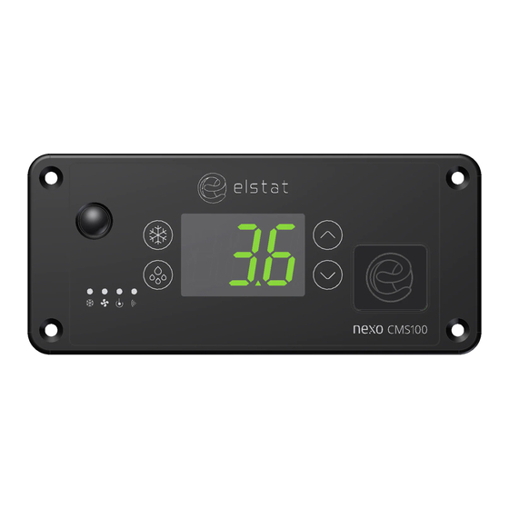
CMS100 Product Manual, Issue 8 Item On display Name Function Motion Sensor Detects motion LED Display Displays the current status of the controller Programmable Port Enables upload of parameters using a dongle 1.3 Overall dimensions The overall dimensions of the controller are shown in the following diagram. -
Page 8: Mounting
If mounted too close the floor, water ingress may occur at the mains or line voltage terminals. Cable routing to the CMS100 controller is critical as water can trace or follow the cable downwards. Therefore, immediately prior to the connection to the controller, a drip loop must be formed in all wiring as shown. -
Page 9: Electrical Connections
CMS100 Product Manual, Issue 8 1.5 Electrical connections Item Description Connectors Compressor Line in Fan(s) Light(s) Product Sensor 12VAC Evaporator Sensor Door Condenser Sensor Appliance Sensor Remote Motion Detector (If applicable) 1.6 Programming port cover When accessing the programming port on the controller fascia, remove the rubber cover and let it hang on the attaching strap. -
Page 10: Wiring Diagram
To remove the potential for damage occurring to, and the potential for failure of, the crimped connection on the mating half of terminals 1 to 4 of the CMS100 Nexo controller it is recommended that only right angle insulated 6.3mm tab connectors, complete with strain relief, are used to terminate these cables. -
Page 11: Relay Ratings
CMS100 Product Manual, Issue 8 1.8 Relay ratings Maximum IEC rating Maximum UL ratings Relay @100-240VAC @ 120VAC Compressor 10 (10) A, p.f. 0.6 16 FLA, 96 LRA Lights 4 (4) A, p.f. 0.6 250W ballast Evaporator fan 4 (4) A, p.f. 0.6 4.4 FLA, 13.1 LRA... -
Page 12: Environmental Ratings
Product Manual, Issue 8 CMS100 1.10 Environmental ratings Characteristic Value IP (Ingress Protection) Rating IP45 Front Fascia, IP24 All Over Maximum operating temperature 55°C (131°F) Minimum operating temperature 0ºC (32ºF) Black polycarbonate, Food grade Housing material (non-contact) Operating control Electronic Thermostat... -
Page 13: Accessories
CMS100 Product Manual, Issue 8 2. ACCESSORIES 2.1 Temperature sensors Temperature sensors are available from Elstat with various cable lengths. To help identify sensor cables during the installation, Elstat can supply sensor cables with blue identification sleeves. For example, if the appliance sensor cable is plain black; the condenser sensor cable can be purchased with a blue identification sleeve. - Page 14 Product Manual, Issue 8 CMS100 2.1.2 Condenser sensor This sensor measures the temperature of the refrigeration system. Excessive condenser temperature is usually due to poor preventive maintenance, such as poorly cleaned condenser, or condenser fan failure. EMS controllers can generate alarms if the refrigeration system temperature rises too high.
-
Page 15: Door Switch
CMS100 Product Manual, Issue 8 2.1.3 Evaporator sensor The evaporator sensor measures the temperature of the evaporator. 2.2 Door switch Door switches are used to detect door openings. They are SELV components that are able to create an open and closed circuit. The Elstat enhanced door switch, and activator, are over-moulded for increased physical protection and resistance to water ingress. - Page 16 Product Manual, Issue 8 CMS100 The alignment of the door switch and activator is critical for the correct operation of the door switch. The table details alignment tolerances. Alignment Dimensions Notes 0mm (0in) Measured when the door is closed and the gap Horizontal (z-dimension) is correct.
-
Page 17: Motion Sensor
CMS100 Product Manual, Issue 8 2.3 Motion sensor Motion sensors are passive infra-red (PIR) devices that detect activity. The diagram shows the detection pattern of motion sensors. The motion sensor must have an uninterrupted view directly in front and to the sides. -
Page 18: Transformer
Overall dimensions of the motion sensor Dimensions of the mounting holes Sample of a mounted motion sensor 2.4 Transformer The CMS100 Nexo controller is powered up via the transformer that is available in two options: 120VAC/50-60Hz - 12VAC Transformer 230VAC/50-60Hz - 12VAC Transformer Page 18 www.nexo.com... -
Page 19: User Guide
CMS100 Product Manual, Issue 8 3. USER GUIDE 3.1 Power-up sequence 8. 8. 8. to confirm that all segments of the display are functioning correctly Platform type and firmware version. (example) Checksum of the parameter set. (example) The display then shows the appropriate display code. For example, the temperature or USE. -
Page 20: Gdc) Firmware Menus
Product Manual, Issue 8 CMS100 3.3 (GDC) Firmware menus The table below describes the controller GDC firmware Sub-menu. Use the Up or Down buttons to scroll through the menu and the Set button to select. Menu Display Description Parameter list Displays the parameters and the parameter values. -
Page 21: The Menu Arrangement
CMS100 Product Manual, Issue 8 3.4 The menu arrangement Set button - press to select - use to increase value - use to decrease value Defrost button - press to return Up button - press to scroll up Down button - press to scroll down Enter Parameter password List (PS) And so on... Test Menu Relay Test Compressor (tSt) (rEL) (CP) Light (LIt) Fault List Analogue (FLt) Test (AnA) (FAn) Buzzer (BUZ) Infrared Half Reset Test (Plr) (Hr) (ALL) Full Reset... -
Page 22: Menu Access
Analogue inputs (temperature sensors and door switch) Motion sensor Should a problem be suspected with CMS100 Nexo controller it is recommended that the test routine is carried out before disconnecting or replacing the controller. The test routine can detect any loose or disconnected cables and check that the controller is connected properly to the lights, fan and compressor. - Page 23 CMS100 Product Manual, Issue 8 3.6.1 Entering the test routine menu Step Action Display Press the Set button The display shows: Enter the appropriate password to access the menu. The display shows: Press the Down button to scroll to the test (tSt) menu...
- Page 24 Product Manual, Issue 8 CMS100 Follow the routine below for Compressor: Action Button Display Test Check Press Select compressor Compressor relay Compressor is running and Press engaged compressor LED is on Compressor relay Compressor stopped running and Press disengaged compressor LED is off Press Defrost to return to the relay test menu.
- Page 25 CMS100 Product Manual, Issue 8 Follow the routine below for Fan: Action Button Display Test Check Press Press Select fan Evaporator fan and the fan LED is Press Fan relay engaged Evaporator fan and the fan LED is Press Fan relay disengaged Press Press Defrost to return to the relay test menu.
- Page 26 Product Manual, Issue 8 CMS100 Follow the routine below for All outputs: Action Button Display Test Check Press All outputs Press Select all outputs Press All outputs engaged All outputs are on Press All outputs disengaged All outputs are off Press Press Defrost to return to the relay test menu.
- Page 27 CMS100 Product Manual, Issue 8 Then follow the routine: Action Button Display Test Check Appliance sensor input Appliance sensor Displayed temperature is as Press temperature expected Press Press Defrost to return to the analogue input test menu Press Door switch...
- Page 28 Product Manual, Issue 8 CMS100 Action Button Display Test Check Press Evaporator sensor input Evaporator sensor Displayed temperature is as Press temperature expected Press Press Defrost to return to the analogue input test menu For future use - Stock sensing...
- Page 29 CMS100 Product Manual, Issue 8 Then follow the routine: Action Button Display Test Check Press Press the Set button to enter the motion sensor test. Place your hand about 300mm from the motion sensor Move your hand from left to right. Check for the following: The display count increments for each detected movement.
-
Page 30: Viewing The Last Three Cooler Faults Witnessed By The Controller (Flt)
Product Manual, Issue 8 CMS100 3.7 Viewing the last three cooler faults witnessed by the controller (FLt) It is possible to view the last three faults and understand problems that have occurred with the cooler. Step Action Display Press the Set button... -
Page 31: Half Reset (Hr)
CMS100 Product Manual, Issue 8 3.8 Half reset (Hr) Half resets are used to clear controller’s self learning matrix in the event that the controller has learned incorrect opening times due to being unable to detect activity correctly. The matrix may require clearing for reasons such as:... - Page 32 Product Manual, Issue 8 CMS100 Step Action Display Press the Up button to change ‘nO’ to ‘yES’ Press the set button to perform half reset The controller should reset and begin the power-up sequence. Page 32 www.nexo.com...
-
Page 33: Viewing Statistics
CMS100 Product Manual, Issue 8 3.9 Viewing statistics Depending on the model, the controllers start gathering a variety of statistics when first powered up. Statistics provide information on the following, dependent on firmware: Activity: Number of motion counts and door openings. - Page 34 Product Manual, Issue 8 CMS100 Display Statistic Description Lowest temperature measured by the appliance sensor during Lowest temperature the last 24 hours. Total number of motion counts since first powered up or last Motion counts full reset Value of the standby temperature disable PEr parameter.
-
Page 35: Controller Alarm Operations
Saving mode. 4.1 ‘Limp home’ functionality As the CMS100 Nexo acts as a diagnostic device, and manages various operational functions of the cooler it serves to prevent faults from becoming critical to the cooler, for example over working of the compressor. -
Page 36: Door Alarms 'Limp Home' Mode
The cooler will operate during this period, cooling the products, while a service engineer visit is scheduled. The table below describes how the CMS100 Nexo controls the cooler during this time and what the end user will see:... -
Page 37: Temperature Sensor Alarms
The limp home aspect of this alarm ensures that the cooler continues to operate with limited disruption to the end user. The cooler will operate, cooling the products, while a service engineer visit is scheduled. The table below describes how the CMS100 Nexo controls the cooler during this time and what the end user will see:... -
Page 38: Refrigeration System Failure (Rsf) Alarms
The refrigeration system will operate - cooling the products - while a service engineer visit is scheduled. The table below describes how the CMS100 Nexo controls the cooler during this time and what the end user will see:... -
Page 39: Cooler And Controller Troubleshooting Tips
CMS100 Product Manual, Issue 8 5. COOLER AND CONTROLLER TROUBLESHOOTING TIPS 5.1 RSF Alarms Refrigeration system failure (rSF) alarms trigger if the set point (SP) temperature is not reached within the time defined by the compressor runtime (Ct) parameter. The controller has detected a problem with the cooling system, please check:... -
Page 40: Condenser Sensor Alarms
Product Manual, Issue 8 CMS100 5.5 Condenser Sensor Alarms The controller has detected an open circuit on the condenser input, please check: The condenser sensor is properly connected to the condenser input on the controller The condenser sensor is reading the correct temperature – Temperature versus resistance: Thermistor is Negative Temperature Coefficient (NTC) The condenser input on the controller is in working order –... -
Page 41: Other Problems
CMS100 Product Manual, Issue 8 5.8 Other Problems 5.8.1 Cooler lights do not switch ON/OFF as expected Note: Enter the service mode via the APP or the In-code test routine via the front panel of controller to ensure that the controllers intended operation is not affecting the result. - Page 42 Product Manual, Issue 8 CMS100 Page 42 www.nexo.com...
-
Page 43: Parameters
Parameter settings are defined by customers and can be loaded and edited automatically, via the XML files, or manually. This section lists the full set of parameters relevant to the CMS100 controller, with their descriptions, ranges and default values detailed for reference. -
Page 44: Parameter Validation
CMS100 6.2 Parameter validation The CMS100 Nexo controller validates the parameter values that have been manually set by the user by checking that the values do not clash with each other. Below is the set of rules the controller validates the parameter values against: SP must be >... - Page 45 CMS100 Product Manual, Issue 8 6.3.2 Differential (dIF) Display Defines the compressor cut-in temperature when added to the set point (SP) Description temperature during the Ready mode. If the differential (dIF) is set too low, for example, less than 2.0°C the compressor may Considerations cycle on the minimum compressor rest time (rt).
- Page 46 Product Manual, Issue 8 CMS100 6.3.5 Delay to saving (dS) Display Defines the delay in switching to the Saving mode from Ready mode. Description The delay starts at the end of the last active 30 minute period of the Ready mode.
- Page 47 CMS100 Product Manual, Issue 8 6.3.8 Refrigeration system failure (Ct) Display Defines the maximum continuous runtime of the compressor without reaching the set point (SP) temperature. Description If the set point (SP) temperature is not reached within this time, the controller enters the RSF Limp home mode.
- Page 48 Product Manual, Issue 8 CMS100 6.3.11 Saving set point (SSP) Display Description Defines the compressor cut-out temperature during the Saving mode. Considerations Must be set above the set point (SP). Range 0.0 to 9.9°C (32 to 50°F) Global default 7.0°C (45°F) 6.3.12 Uninterrupted pull down (IPd)
- Page 49 CMS100 Product Manual, Issue 8 6.3.14 Defrost interval (dE) Display Defines the period between the end of defrost cycle and beginning of the next defrost Description cycle. A time-based defrost cycle helps improve evaporator efficiency. In the event of power loss, the defrost interval (dE) is not maintained. The defrost interval is reset.
- Page 50 Product Manual, Issue 8 CMS100 6.3.17 Fan cycle off (FCF) Display Description Defines the inactive period of the evaporator fan while the compressor is switched off. Considerations Fan cycle is the fan cycle on (FCO) time + the fan cycle off (FCF) time.
- Page 51 CMS100 Product Manual, Issue 8 6.3.20 Motion sensor enable (Sn) Display Description Enables the input from the motion sensor. Considerations Must be disabled if a motion sensor is not fitted. Range 0 (disabled) or 1 (enabled) Global default 1 (enabled) 6.3.21 Display stability (d2) Display Defines the rate of change of the displayed temperature.
- Page 52 Product Manual, Issue 8 CMS100 110-120V line 220-240V line voltage voltage Disabled Note: Voltage measurement is accurate to ± 10% Caution Low voltage protection is not calibrated and actual performance can be influenced by several factors. Therefore, total protection cannot be guaranteed.
- Page 53 CMS100 Product Manual, Issue 8 6.3.24 Defrost termination temperature (dtd) Display Defines the temperature to end the defrost cycle. Description Ending defrost cycles on temperature minimizes the duration of defrost cycles. • Must be set above the set point (SP) plus differential (dIF) temperature.
- Page 54 Product Manual, Issue 8 CMS100 The table below describes the values for activity frequency (AF). Value Name Description Low frequency 1 door opening or 1 motion count Medium frequency 1 door opening or 3 motion counts High frequency 2 door openings or 6 motion counts The controller runs continuously for 48 hours in the ready mode.
- Page 55 CMS100 Product Manual, Issue 8 6.3.28 Buzzer enable (b0) Display Enables or disables a warning buzzer for alarm conditions. Door open alarms always Description sound the warning buzzer regardless of this parameter setting. Following alarm conditions trigger the buzzer: Refrigeration system failure (rSF) Sensor failure (PF1, PF2). Ht alarms Considerations Door alarms sound the buzzer as standard.
- Page 56 6.3.33 Shelf data enable (ShF) Display Description Option to allow the Nexo controller to log stock sensing data to be sent to the cloud. Input will still be operational when viewed via the test routine (tSt). Considerations Stock sensing hardware currently unavailable.
-
Page 57: Approvals
CMS100 Product Manual, Issue 8 7. APPROVALS 7.1 Product Approvals Conformité Européene / European Conformity (CE) EN60730-1 EN60730-2-9 European Norms Electrical Certification (ENEC) EN60730-1 EN60730-2-9 International Electrotechnical Commission (IEC) IEC60730-1 IEC60730-2-9 Glow wire: IEC60335-1 North America (including Canada) - UL mark (Component Recognition) -
Page 58: Bluetooth Approvals
Product Manual, Issue 8 CMS100 7.2 Bluetooth Approvals Agência Nacional de Telecomunicações (ANATEL) Resolução Anatel nº 242 * See note below Bluetooth Special Interest Group (SIG) Bluetooth ® Qualified Design La Comisión Nacional de Comunicaciones (CNC) Resolución SC 729/80 - Resolución SC 784/87 European Telecommunications Standards Institute (ETSI) EN300 328 V1.8.1... -
Page 59: Glossary Of Terms
CMS100 Product Manual, Issue 8 8. GLOSSARY OF TERMS 8.1 Acronyms The table below explains the meanings of the most common acronyms used in this manual. Acronym Meaning ems or Energy Management The Elstat range of products in this group are all energy management System systems. - Page 60 CMS100 Product Manual Installation & set up guide Accessories User guide Troubleshooting Elstat Ltd Astra Business Centre, Roman Way, Preston, Lancashire PR2 5AP, UK www.nexo.com info@nexo.com...
Need help?
Do you have a question about the CMS100 and is the answer not in the manual?
Questions and answers