Table of Contents
Advertisement
Quick Links
Advertisement
Table of Contents

Related Manuals for FotoFinder bodystudio ATBM master


Summary of Contents for FotoFinder bodystudio ATBM master
- Page 2 FotoFinder bodystudio ATBM master Original user manual Please read these original operating instructions carefully before using the device and always keep it easily accessible! Copyright © 2024 FotoFinder Systems GmbH Status: 25.06.2024...
- Page 3 FotoFinder Systems GmbH Industriestraße 12 84364 Bad Birnbach Germany www.fotofinder.de info@fotofinder.de Tel.: +49 (0) 8563 97720-0 Fax: +49 (0) 8563 97720-10...
-
Page 4: Table Of Contents
3.13.6 EMC tested cables, transformers and accessories.............. 28 3.13.7 Recommended minimum distance between portable and mobile RF communication devices and the FotoFinder device ..................29 3.14 Moving the mounted device ..................... 30 3.15 Maximum load of the components ................... 31 4 Installation ........................ - Page 5 4.2.2 LAN connection ........................34 4.2.3 Power supply plug ....................... 34 Main voltage settings on the system cart ................. 35 Use in a network ........................35 Connecting the camera with the PolFlash XE DX2 (with Zoom Motor) and the computer ..36 Connecting the camera with the PolFlash XE (without Zoom Motor) and the computer ..
-
Page 6: About These Operating Instructions
The system is suitable for both medical imaging and photo documentation of aesthetic facial and body treatments. The development and production of all products of FotoFinder Systems GmbH is carried out in accordance with the current ISO 13485 standards. -
Page 7: Presentation Of Warning Labels
1.3 Presentation of warning labels In the operating instructions, warnings are marked with a signal word panel. Warnings are introduced with signal words expressing the extent of the hazard. Observe all warnings to avoid accidents, personal injury and damages. The following signal words and symbols are used in the operating instructions: This is the general hazard sign. -
Page 8: Information On The Device Label
Frequency Mains frequency Unique serial number of the device Month and year of manufacture UK Conformity Assessed Party responsible for UK: FotoFinder Systems Ltd., 100 Addison Road, W148DD London, United Kingdom Output Nominal voltage/nominal current at the isolating transformer output... -
Page 9: Explanation Of The Symbols
Electronic user manual 1.5 Explanation of the symbols Warning: entanglement hazard Crush hazard Warning: laser beam Warning: laser beam Do not stand on surface Do not push this device component Equipotential bonding Indicates the Swiss representative: Johner Medical Schweiz GmbH, Tafelstattstrasse 13a, 6415 Arth, Switzerland Tab. -
Page 10: System Components And Technical Data
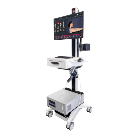
System components and technical data 2 System components and technical data 2.1 Overview... - Page 12 System components and technical data The FotoFinder bodystudio ATBM master comprises the following components: Fig. 1: FotoFinder bodystudio ATBM master ATBM tower with automatic rail Camera carriage Monitor Toothed belt Camera Energy chain PolFlash XE (flash system) Compartment for docking station...
-
Page 13: Positioning Mat
The Laser Liner facilitates reproducible patient positioning by projecting a red line onto the positioning mat. Fig. 2: Laser Liner on ATBM master Tower Technical information Model: FotoFinder Laser Liner (USB) Wavelenght: 650 nm (visible) Output: 5 mW Beam duration: <1.5mm@3m... -
Page 14: Polflash Xe
System components and technical data 2.4 PolFlash XE PolFlash XE is the flash unit on your FotoFinder bodystudio ATBM master system. Fig. 3: PolFlash XE on an ATBM tower Flash tubes for polarised captures Flash tubes for non-polarised captures Camera lens... - Page 15 Technical data Model: PolFlash XE Input: DC 24.0 V, 5 A Power: 120 W Output: DSLR DC 8.0 V The product is labelled as follows: Top: Laser Class 1: Bottom: Type plate: Laser label:...
-
Page 16: Life Cycle
However these components should be visually inspected from time to time for wear damage (rail, camera holder) and stretching of the belt. If any of these components are no longer working correctly, they must be replaced by a FotoFinder technician. -
Page 17: Safety
3 Safety 3.1 Adherence to the operating instructions NOTE Every person assigned to work with the system must have read and understood these operating Safety instructions and particularly the chapter on The knowledge and observation of the applicable contents is a prerequisite for protecting users and patients from hazards and to prevent user errors. -
Page 18: Intended Use
Documentation of naevi Non-invasive, rapid, digital dermoscopy of intact skin The system has been designed for and can only be used together with the FotoFinder Universe software. In the process, various views are captured using a single-lens reflex camera, and then stored on the system. -
Page 19: User Groups
3.3 User groups The following target groups with the required qualifications may work on the device: Target group Qualification Physician Professionally qualified as physician Practice personnel Trained and instructed and professionally qualified through a completed apprenticeship in specialized medicine Service/Hospital technician At least 3 years of professional experience in the medical technological sector We have allocated target groups to life below. -
Page 20: Use Environment
Only capture persons with a body height of between 130 cm and 200 cm. Full captures of larger and smaller persons are not supported (not relevant for face captures with the portrait stand). NOTE Feel free to contact FotoFinder Systems to discuss the best design for your photography room. Please contact us! NOTE... -
Page 21: Patient Population
The device is designed for clinical images as stated in the chapter Patient target group . For a detailed list of ICD codes, please contact info@fotofinder.de. The following parts of the body are suitable for examination with the FotoFinder dermatoscope: Intact skin surface of the entire body Scalp Nails The device is not designed for capturing images of mucous membranes, eyes or natural or artificial body orifices. -
Page 22: Residual Risks
Safety 3.9 Residual risks WARNING Despite compliance with all regulations and the implementation of risk-minimizing measures, not all risks can be completely excluded. Residual risks that exist in connection with the use of the product are listed below. Improper operation by untrained personnel and non-compliance with the specified safety and warning instructions may result in harm to the patient or operator. -
Page 23: Ambient Conditions
If you have removed any lenses, do not rest them on the glass lens, which could be scratched. Before cleaning, disconnect the complete system from the power supply. If the camera makes any unusual noise, emits smoke or unusual odor, disconnect the whole system from the power outlet immediately and contact FotoFinder Systems. -
Page 24: Operator Duties
A final production check is carried out on the entire system or, if applicable, the components as per EN 62353 during in-house production. When commissioning is performed by a FotoFinder contact, the operator is encouraged to check and confirm the values of the in-house inspection. -
Page 25: Electric Safety
Do not remove the casing of the device: there is hazardous current inside. The casing must be correctly mounted. All repairs and replacements must be made by a qualified FotoFinder representative. Check the casing and cables before use. Do not use the device and disconnect it completely from the power supply, if the casing is cracked, chipped or broken, or if the casing or the cables are damaged. -
Page 26: Esd
Interference) requirements, an electromagnetic field can cause momentary disturbance of the camera live image. If this occurs often, FotoFinder Systems suggests a review of the environment in which the system is being used, to identify possible sources of interference. These could be from other electrical devices used within the same or a nearby room. -
Page 27: Emc
3.13.4 EMC The testing for EMC (Electromagnetic Compatibility) of this system has been performed according to the international standard for EMC with medical devices (IEC 60601-1-2:2014+A1:2020). This IEC standard complies with the European norm (EN 60601-1-2:2015+A1:2021). European publication Surroundings of professional medical Deviation from basic facilities EMC standards or... -
Page 28: Instructions And Manufacturer's Information On Electromagnetic Radiation
Radiation test Compliance Electromagnetic environment - Directive RF emission Group 1 The FotoFinder device is not likely to cause CISPR 11 interference with other electronic devices in the vicinity. RF emission Class A... -
Page 29: Recommended Minimum Distance Between Portable And Mobile Rf Communication Devices And The Fotofinder Device
3.13.7 Recommended minimum distance between portable and mobile RF communication devices and the FotoFinder device This product is intended for use in an electromagnetic environment where the radiated RF disturbances are controlled. The user of this device can help prevent electromagnetic interference by... -
Page 30: Moving The Mounted Device
Safety 3.14 Moving the mounted device Basically, the built-up device should not be moved unnecessarily, as it could get damaged. Should it nevertheless be necessary, please note the following: The device trolley has a weight of 80 kg / 176.6 lbs. Therefore, for reasons of ergonomics, it is not intended to be carried or lifted. -
Page 31: Maximum Load Of The Components
3.15 Maximum load of the components FotoFinder bodystudio ATBM master: The maximum load of the individual device components must not be exceeded, otherwise the device could be damaged. Please keep to the specified load limits. You will also find these on the corresponding labels on your device. -
Page 32: Installation
Installation 4 Installation DANGER A device of Protection Class I Danger of injury due to electric shock. Connect the device to a properly grounded power outlet only. DANGER Danger of electric shock due to high voltage! Severe injury or death could result when touching an energized conductor. Work on electrical systems may only be conducted by authorized electricians. -
Page 33: Delivery Scope
4.1 Delivery scope Your FotoFinder product is dispatched as largely assembled. However, before commissioning, the following parts have to be attached and cabled. This task is performed by the respective FotoFinder consultant or the FotoFinder distributor. PolFlash XE... -
Page 34: Connections On The System Cart
Installation 4.2 Connections on the system cart Fig. 5: Connections on the cart 4.2.1 The potential equalization plug Before you start up the device and connect the mains plug, first connect the potential equalization cable connected through the main potential equalization rail to the designated socket for potential equalization (POAG) (cf. -
Page 35: Main Voltage Settings On The System Cart
FotoFinder bodystudio ATBM master T 4.0A T 2.0A 4.4 Use in a network It is possible to operate the system in a network with several FotoFinder Universe clients. The FotoFinder bodystudio ATBM master includes a galvanic network isolator as per IEC ®... -
Page 36: Connecting The Camera With The Polflash Xe Dx2 (With Zoom Motor) And The Computer
Installation 4.5 Connecting the camera with the PolFlash XE DX2 (with Zoom Motor) and the computer Fig. 6: PolFlash XE DX2 The polarising filter at the front of the camera's lens is correctly mounted when the lettering Fig. 7: PolFlash XE DX2 from above... - Page 37 The PolFlash XE DX2 including the mounted camera must be attached to the ATBM Tower by placing it on the camera slider and fixating it from below with two screws and lock washers. NOTE To avoid damaging the device, do not compress the lock washers too much. Tighten to a maximum of 1 Nm.
- Page 38 Installation ATTENTION Do not (e.g. during cleaning) apply any pressure to the PolFlash XE lens or camera. The device could get damaged and the fine adjustments could be changed. This also applies to the lenses of the flashes (the Fresnel lense structure could be damaged) the lenses of the camera and the polarization filter the casing and the Zoom Motor...
-
Page 39: Connecting The Camera With The Polflash Xe (Without Zoom Motor) And The Computer
4.6 Connecting the camera with the PolFlash XE (without Zoom Motor) and the computer Fig. 10: Fully mounted camera on the PolFlash XE Fig. 11: Individual system parts (partly pre-assembled at the factory) PolFlash XE with pre-assembled metal adapter plate for the camera Digital camera (model may deviate) with already inserted battery dummy and power supply cable, as well as a flash adapter Assembly material... - Page 40 Installation Connect the assembly material as illustrated in the adjacent figure: Two spring washers are placed onto the screw with camera thread. Place the camera onto the metal adapter plate while carefully pushing the lens into the round opening on the PolFlash XE. Turn the whole thing over so that you can reach the bottom of the PolFlash XE while holding the camera.
-
Page 41: Checking The Laser Liner
ATTENTION Please observe all safety instructions for the PolFlash XE in this manual (cf. 4.5). 4.7 Checking the Laser Liner The Laser Liner is fully assembled on delivery. Check the distance from the Laser Liner to the laser line projected onto the floor. It must be 111.5 cm. -
Page 42: Operation
Operation 5 Operation CAUTION The camera positioning system's movements may cause injury. Never grab the chain or belt, especially when the camera is moving up or down the rail. Always keep clear at least 30 cm to all moving parts of the camera positioning system (automatic chain, camera slider). -
Page 43: Visual Inspection Before Use
Before cleaning the camera, please disconnect the complete system. If the camera makes any unusual noises, emits smoke or unusual odor, disconnect the whole system immediately and contact FotoFinder Systems GmbH. 5.1 Visual inspection before use Before each use, check the system for visible damage. -
Page 44: Switching On The Device
Switch on the Laser Liner. A red projection line appears on the floor. Align the projection line of the Laser Liner to the designated line of the FotoFinder positioning mat. Start FotoFinder Universe*. Position the patient on the positioning mat in the posture specified by the body manikin in the software. -
Page 45: Operating The Canon Slr Camera
Focus point is set to wide area When using a full-frame camera (e.g., Canon EOS 6D, Canon EOS 5Ds, Canon EOS R), the focus point may have to be manually adjusted. If you require assistance, please contact FotoFinder Systems or your local consultant. -
Page 46: Ending Operations
Operation 5.5 Ending operations Close Universe and any open software modules. This will also automatically log you out of the software. Shut down the computer. Press the main switch on the device. Disconnect the power plug from the power supply. The Canon camera should always be left switched on, even when you are not using it. -
Page 47: Cleaning And Disinfection
If you have removed any lenses, do not rest them on the lens, which could be scratched. Before cleaning the camera, please disconnect the complete system. If the camera makes any unusual noises, emits smoke or unusual odor, disconnect the whole system immediately and contact FotoFinder Systems GmbH. ATTENTION Only clean the POLFLASH XE dry. -
Page 48: Cleaning The Device
Cleaning and disinfection 6.1 Cleaning the device Before cleaning, disconnect the entire system from the power supply. Clean the case, control panels, control elements and the screen with a soft cloth moistened slightly with a mild detergent. 6.2 Disinfection of the device Commercially available disinfectants that are approved for surface disinfection or disinfection wipes can be used. -
Page 49: Settings
7 Settings You can adjust the settings of your device in the software. Settings You will find the button at the top right of the the dashboard in the FotoFinder Universe software. 7.1 Devices 7.1.1 Automatic Tower Devices. You can find some functional settings for the ATBM Tower under Camera profile: Here you can preselect a camera profile as default, e.g. -
Page 50: Maintenance
Warning! This device must not be modified without the approval of the manufacturer! To ensure your system functions perfectly, subject your device to periodic inspections and repeat checks. At FotoFinder Systems we recommend that you carry out repeat checks as per EN 62353 every 12 months. -
Page 51: Malfunction And Troubleshooting
PolFlash XE flash lens. WARNING Do not continue using the PolFlash XE with a blown flash tube! Switch off the FotoFinder ATBM master and disconnect it from the power supply. Please contact your distributer or FotoFinder contact to make an appointment for repair or replacement. -
Page 52: The Motor Has Stopped Working
FotoFinder Systems GmbH. Check all connection cables at the back of the computer. Close the FotoFinder Universe software and shut down the computer. Disconnect the unit from the power supply for a few seconds. Restart the computer and the FotoFinder Universe software. -
Page 53: Disposal
10 Disposal ATTENTION Risk of environmental damages caused by improper disposal. For disposal, observe local regulations and legal requirements. By properly disposing of and recycling old equipment and used components, natural resources can be conserved and the environmental impact minimized. Therefore, please note the following points: The operator is responsible for proper disposal. -
Page 54: Glossary
Optical positioning system for the required, optimum alignment of the positioning mat PolFlash XE FotoFinder's polarised flash system for the single-lens reflex camera. Guarantee of capture with consistent illumination and quality NOTE *There are separate instructions for use for this FotoFinder product. -
Page 55: Appendix
12 Appendix... - Page 56 Appendix...
Need help?
Do you have a question about the bodystudio ATBM master and is the answer not in the manual?
Questions and answers