
Related Manuals for Tornado Sentry TMEV125S


Summary of Contents for Tornado Sentry TMEV125S
- Page 1 Installation & Commissioning Instructions TMEV125S TMEV125H Multi Room Continuous Running Mechanical Extract Ventilation IPX2 220-240V~50Hz PLEASE READ INSTRUCTIONS IN CONJUNCTION WITH THE ILLUSTRATIONS. PLEASE SAVE THESE INSTRUCTIONS...
- Page 2 Installation and Wiring Instructions for the Multi Room Extract Units. IMPORTANT: READ THESE INSTRUCTIONS BEFORE COMMENCING THE INSTALLATION • Do not install this product in areas where the following may be present or occur: • Excessive oil or a grease laden atmosphere. •...
-
Page 3: Installation
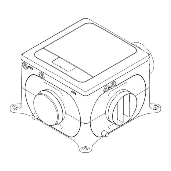
INTRODUCTORY NOTES The MEV units are designed for simultaneous extract ventilation of multiple areas such as bathrooms, kitchens and toilets. The units use a highly efficient backward curved centrifugal motor impeller set and are designed for continuous 24-hour use. Depending on the model, they feature either 3 or4 settable speeds and can be configured to change speed based on a wide range of sensor or control inputs as depicted below Switched Analogue... - Page 4 See the dimensional details below for the mounting hole positions. -Spigot diameters are 125mm...
- Page 5 Base mounted Installation with ducting radiating out horizontally. Vertically mounted Installation with the exhaust spigot at top. The electrical connections must come out of the bottom of the unit in order to maintain the water ingress protection.
- Page 6 iii. Ceiling mounted Installation with ducting radiating out horizontally. WIRING WARNING: THE UNIT AND ANCILLARY CONTROL EQUIPMENT MUST BE ISOLATED FROM THE POWER SUPPLY DURING THE INSTALLATION / OR MAINTENANCE. THIS UNIT MUST BE EARTHED. To remove the cover, use a coin or similar; depress the retaining tabs via the slots in the side of the unit. With the power off, connect a suitable mains power cable from a switched, fused spur to the screw terminal block.
-
Page 7: Connection Diagram
CONNECTION DIAGRAM Main power connections Low voltage connections... - Page 8 A: Main power connections The LS1, LS2 and NS terminals are electrically isolated. Note: Neutral link between 2 & 6 should be removed if different RCD protection circuits are used for mains power & Live Switch connections. Note: Ensure all live & neutral are isolated before servicing. This appliance incorporates an earth connection for functional purposes only.
-
Page 9: Unit Adjustment
COMMISSIONING Unit Adjustment 1. Commissioning and configuration on all products is supported by the 3 digit user interface and associated push buttons. 2. When powered on, the unit will display the firmware revision number, after a few seconds the unit will display the first option in the menu structure (see below). - Page 10 User Configurable Parameters Display Function Selections Default text Low speed 1 to 97% motor speed Normal speed 2 to 98% motor speed Boost speed 3 to 99% motor speed Purge Speed 4 to 100% motor speed Live switch 1 Low, Boost or Purge speed Live switch 2 Low, Boost or Purge speed Boost...
-
Page 11: Servicing And Maintenance
SERVICING & MAINTENANCE WARNING: THE FAN AND ANCILLARY CONTROL EQUIPMENT MUST BE ISOLATED FROM THE POWER SUPPLY DURING MAINTENANCE. At intervals appropriate to the installation, the fan should be inspected and cleaned to ensure there is no significant buildup of dirt or other deposits. To inspect the inside of the product isolate the power, use a coin or similar to depress the cover retention clips. -
Page 12: Product Spec
Product Spec Tornado Sentry Name: TMEV125S TMEV125H Model ID (Stock Ref.) : SEC Class SEC Value ('Average') -27.2 SEC Value ('Warm') -11.7 SEC Value ('Cold') -54.3 Label Required? (Yes/No=Out of scope) Declared as: RVU or NRVU/UVU or BVU RVU/UVU Speed Drive...
Need help?
Do you have a question about the Sentry TMEV125S and is the answer not in the manual?
Questions and answers