Table of Contents

Related Manuals for Diamond Systems EPS-12002L


Summary of Contents for Diamond Systems EPS-12002L
- Page 1 EPS-12002L Ethernet Switch User Manual Revision 1.3 © Copyright 2024 Diamond Systems Corporation FOR TECHNICAL SUPPORT www.diamondsystems.com PLEASE CONTACT: Site: www.diamondsystems.com/support/ Email: support@diamondsystems.com...
-
Page 2: Table Of Contents
Privilege Commands .......................... 32 SNMP Commands ..........................32 SNTP Commands ..........................33 Radius Server Commands ......................... 33 Banner Commands ..........................35 Terminal Commands .......................... 35 Reload Command ..........................35 Firmware Commands ......................... 35 EPS-12002L User Manual Rev 1.1 Diamond Systems... - Page 3 Ping Commands ..........................35 Debug Commands ..........................36 Security Commands ........................... 36 Monitor Commands ..........................36 Command Parameter and Syntax Examples ..................... 37 IP Configuration ..........................37 Port Configuration ..........................37 Changing the Switch Password ......................37 Setting Up VLANs ..........................37 SNMP Configuration ..........................
-
Page 4: Important Safe Handling Information
Diamond Systems recommends that all our boards be stored only in individual ESD-safe packaging units. If multiple boards are stored together, they should be contained in bins with dividers placed between the boards. - Page 5 Short Circuit Failures: There are various causes for a short circuit to occur and disrupt the electrical flow of the circuitry, causing the board to malfunction or cease to function entirely. A short can be difficult to identify since its symptoms are often not visible. Some common causes such as slipping of a metal screwdriver tip, or a screw dropping onto the board while it is powered-up, can cause a short between a power pin and a signal pin on a component, leading to circuit damage, over-voltage, and power supply problems.
-
Page 6: Introduction
The EPSM-10GX switch module supports 12 1Gbe ports natively and up to 12 additional 1Gbe ports with the addition of a 12-port PHY on the carrier board. This PHY is not included on the EPS-12002L for size considerations. For a higher port count solution, please consider Diamond’s EPS-24G4X: www.diamondsystems.com/products/eps24g4x... - Page 7 There are two Ethernet software solutions available for EPS-12002L, by Microchip. Both support a comprehensive set of Ethernet Switching capabilities, designed to support Managed L2 and L3 Enterprise Switches such as: • Port Control and Monitoring Features • QoS Control •...
-
Page 8: Functional Overview
3. FUNCTIONAL OVERVIEW Block Diagram Figure 3-1: EPS-12002L Ethernet Switch Feature Description EPSM-10GX Switch Module The EPSM-10GX Module is based on the Microsemi VSC7444 SMB/SME Industrial Gigabit Ethernet Switch with up to 24 ports supporting a combination 6x QSGMII ports and 2x 10G SFI Ethernet ports. -
Page 9: Copper Ports
Copper Ports EPS-12002 supports 12x 10/100/1000Mbps copper ports via 2mm rugged latching connector. Each latching connector supports 4x ports. On board magnetics for each copper ports are provided. SFP+ Ports EPS-12002 supports 2x SFP+ ports for 10G ethernet interface directly from EPSM-10GX module via 2nos of stacked SFP+ connector. -
Page 10: Mechanical Drawing
4. MECHANICAL DRAWING Figure 8-3 delineates the Top View Mechanical Dimensions of the EPS-12002 Carrier Board. Figure 4-1: Dimensions of EPS-12002 Carrier Board Figure 8-4 shows the Mechanical Dimensions of the EPSM-10GX and EPS-12002 Assembled Modules with customized Heat Sink. -
Page 11: Board Layout
5. BOARD LAYOUT The following image displays the Top Layout of the EPS-12002 Carrier Board with Jumper Locations. A description of the Key Integrated Circuits and Connectors is tabulated below. Figure 5-1: EPS-12002 Carrier Board Top View Connector Locations IO Connectors EPS-12002 CARRIER BOARD Connector Description... -
Page 12: I/O Connectors
6. I/O CONNECTORS Connector Pin-out and Signal Description High-speed B2B Connectors: J1 and J2 The EPS-12002 Carrier Board contains 2x 120 pin 0.5mm pitch high-speed connectors that accommodate 12x 1 Gbps copper ports, 3x QSGMII ports, 2x 10G ports, power, and other sideband signals. - Page 13 Signal Signal Pin No. Pin No. GND_SIGNAL GND_SIGNAL RTX4CN RTX4AN RTX4CP RTX4AP GND_SIGNAL GND_SIGNAL RTX5DN RTX5BN RTX5DP RTX5BP GND_SIGNAL GND_SIGNAL RTX5CN RTX5AN RTX5CP RTX5AP GND_SIGNAL GND_SIGNAL RTX6DN RTX6BN RTX6DP RTX6BP GND_SIGNAL GND_SIGNAL RTX6CN RTX6AN RTX6CP RTX6AP GND_SIGNAL GND_SIGNAL RTX7DN RTX7BN RTX7DP RTX7BP GND_SIGNAL...
- Page 14 Table 6-1: J2 Connector Signal Description Connector on EPS-12002 Carrier: Samtec ERM5-060-05.0-L-DV Mating Connector on EPSM-10GX Module: Samtec ERF5-060-05.0-L-DV-K Signal Signal Pin No. Pin No. GND_SIGNAL GND_SIGNAL SFPPLUSA_RXD_N SFPPLUSB_RXD_N SFPPLUSA_RXD_P SFPPLUSB_RXD_P GND_SIGNAL GND_SIGNAL SFPPLUSA_TXD_N SFPPLUSB_TXD_N SFPPLUSA_TXD_P SFPPLUSB_TXD_P GND_SIGNAL GND_SIGNAL B_PCIE_T_P QSGMII_P21_P24_RXD_P B_PCIE_T_N QSGMII_P21_P24_RXD_N...
- Page 15 Signal Signal Pin No. Pin No. LED_PWM SLED0_DO GND_SIGNAL PCIEWAKE NINT_PHY1 NSYSRESET GND_SIGNAL GND_SIGNAL RTX9DN RTX9BN RTX9DP RTX9BP GND_SIGNAL GND_SIGNAL RTX9CN RTX9AN RTX9CP RTX9AP GND_SIGNAL GND_SIGNAL RTX10DN RTX10BN RTX10DP RTX10BP GND_SIGNAL GND_SIGNAL RTX10CN RTX10AN RTX10CP RTX10AP GND_SIGNAL GND_SIGNAL RTX11DN RTX11BN RTX11DP RTX11BP GND_SIGNAL...
-
Page 16: Cpld Programming Header: J11
CPLD Programming Header: J11 The EPS-12002 Carrier Board integrates a CPLD to implement the Ethernet LED Logic The LED status signals on the Main Board are transmitted through a serial bus over high-speed B2B connector. The following Table describes the pin and signal specifications of the CPLD Programming Header. Connector Type: 2.54mm TH Vertical Pin Header Pin No Pin Signal... -
Page 17: Serial Interface: J6
RXD (Input) Power Input: J14 The EPS-12002L Carrier Board operates on a wide range of power supply of +7V to +34VDC. Power is supplied through an 8-pin Latching Connector. The pin-out description for input power is shown below. Connector Number: Samtec IPL1-102-01-L-D-RA-K-ND Right Angle Housing: IPD1-02-D-K Crimp Terminal: CC79R-2024-01-F The following diagram depicts the Front View of the Power Connectors. -
Page 18: Assembling Or Disassembling The Switch Module
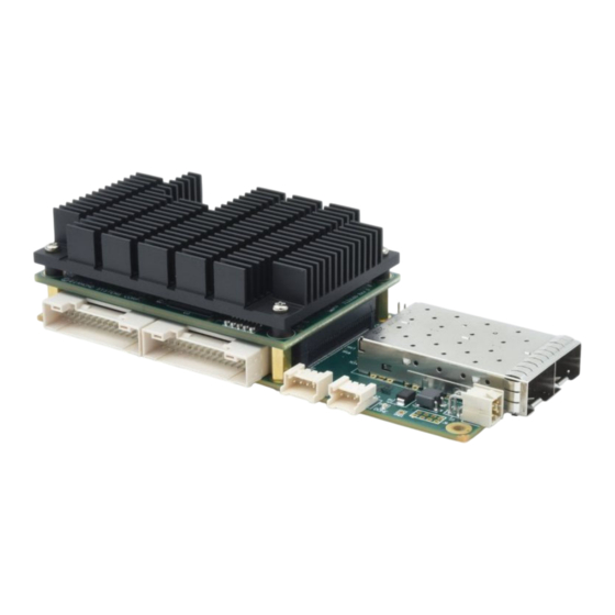
1. The following Figure depicts the BOTTOM view of the EPSM-10GX Module. Figure 7-1: EPSM-10GX Module B2B Connectors 2. The following Figure depicts the TOP view of the EPS-12002L - Carrier Board. The Connectors marked J1 and J2 correspond to the Connectors marked J1 and J2 on the EPSM-10GXBoard depicted above. - Page 19 The following Figure shows the Top View of the assembled unit consisting of the carrier board, EPSM switch module, and heat sink. (A model with heat spreader is also available.) Figure 7-3: EPSM-10GX+ EPS-12002L Module Assembled...
-
Page 20: Cable Kit
8. CABLE KIT The EPS-12002L switch uses cable kit part no. CK-EPS12000, consisting of the cables listed below. Drawings for all cables are available at the following link: https://www.diamondsystems.com/products/cables Cable part no. Quantity Description 6981508 Quad Ethernet cable with panel mount RJ-45 jacks... -
Page 21: Getting Started
3. Connect a LAN cable between the PC to any one of the desired ports on the cable(s) connected to the EPS-12002L - Switch as instructed in Step 3 4. Connect the power cable Part Number 6981507, from the connector J7 to a regulated power supply with +12V nominal or +7V to +34V. -
Page 22: Web Interface And Cli Overview
10. WEB INTERFACE AND CLI OVERVIEW The Command Line Interface (CLI) is a command Line or Text-Based-User Interface with no screen editing capabilities. In this interface, a User types commands and responds to prompts using Syntax and Parameters which are promptly executed by the system. The CLI can be accessed directly via the RS-232 serial connection. -
Page 23: Using The Cli Interface
11. USING THE CLI INTERFACE Making an Initial Connection Serial Line Requirements: • 115200 baud • 8-bit data • No parity • 1 stop bit Login Information Username: admin Password: {none} The Board is configured with the default IP address 192.168.1.60 to enable access to the Web Interface. On access, it enables the User to enter the Admin panel and change/modify settings. -
Page 24: Accessing Help
Accessing Help For assistance press the question mark ? symbol or type Help on the keyboard or type the full or partial command followed by a question mark ?. Selecting the question mark ? symbol will list all the commands on the screen. The help information displayed depends on the context in which help has been requested. -
Page 25: Resetting System To Factory Defaults
Resetting System to Factory Defaults The default command in association with different parameters, executes specific functions, such as resetting the configuration of the Switch to factory defaults while retaining other configurations, or resetting all configurations to default settings. The following syntax resets the configuration of the Switch to factory defaults. # reload defaults # NOTE: On execution, only the IP configuration is retained. -
Page 26: Mac Commands
(config)# ip igmp snooping (config)# ip igmp snooping vlan <v_vlan_list> (config)# ip igmp unknown-flooding 6. To view IGMP snooping and the IGMP router port status: # show ip igmp snooping [ vlan <v_vlan_list> ] [ group-database [ interface ( <port_type> [ <v_port_type_list> ] ) ] [ sfm-information ] ] [ detail ] # show ip igmp snooping mrouter [ detail ] 7. -
Page 27: Vlan/Pvlan Commands
VLAN/PVLAN Commands The following syntax can be used to configure the VLAN of Access Ports or Access VLANs. Ports in other modes are members of all VLANs specified in the Allowed VLANs field. Private VLANs can be added or deleted. Port members of each Private VLAN can be added or removed. Private VLANs are based on the source port mask, and there are no connections to VLANs. -
Page 28: Lacp Commands
# clear dot1x statistics [ interface ( <port_type> [ <v_port_type_list> ] # dot1x initialize [ interface ( <port_type> [ <plist> ] ) ] # show dot1x statistics { eapol | radius | all } [ interface ( <port_type> [ <v_port_type_list> ] ) ] # show dot1x status [ interface ( <port_type>... -
Page 29: Access-List Commands
(config)# access management <access_id> <access_vid> <start_addr> [ to <end_addr> ] { [ web ] [ snmp] [ telnet ] | all } (config)# no access management (config)# no access management <access_id_list> # clear access management statistics # show access management [ statistics | <access_id_list> ] Access-List Commands The following command syntaxes can be used to set the Access List Ace ID, Rate Limiter in pps or kbps, disable or clear Access List statistics, and view Access List Ace status and statistics. -
Page 30: Green-Ethernet Commands
send per second, must be set. If the number is exceeded, the transmission of the next BPDU will be delayed. The following command syntaxes can be used to enable or disable Spanning Tree mode. To set an interval time before a port in the error-disabled state can be enabled: (config)# spanning-tree aggregation (config)# spanning-tree mode { stp | rstp | mstp } (config)# spanning-tree edge bpdu-filter... -
Page 31: Thermal-Protect Commands
The following commands can be issued to disable EEE optimizations for the LEDs and view the status of the Green-Ethernet LEDs. (config)# no green-ethernet eee optimize-for-power (config)# no green-ethernet led interval <0~24> (config)# no green-ethernet led on-event [ link-change ] [ error ] # show green-ethernet [ interface ( <port_type>... -
Page 32: Privilege Commands
Privilege Commands The following Privilege commands are limited to the O/S implemented on the board. Both, Linux and Windows CLI are Text-Based-User Interfaces and execute tasks based on similar CLI principles. However, though the command parameters and syntaxes are similar and perform the same functions on some levels, they differ in many ways. -
Page 33: Sntp Commands
To view or disable the set SNMP server settings: (config)# no snmp-server (config)# no snmp-server version (config)# no snmp-server security-to-group model { v1 | v2c | v3 } name <security_name> (config)# no snmp-server access <group_name> model { v1 | v2c | v3 | any } level { auth | noauth | priv } (config)# no snmp-server community v2c (config)# no snmp-server community v3 <community>... - Page 34 Global Retransmit number for which RADIUS request is sent to a server that has stopped • responding. Dead Time Interval for which no new RADIUS requests are sent to a server that has failed to • respond to previous requests. NOTE: Setting the deadtime will stop the Switch from continually trying to contact a server that has been determined to be dead.
-
Page 35: Banner Commands
Banner Commands A Banner is a message presented to a User and can be configured when the message is displayed. It can be defined before and after Login using the following commands: (config)# banner [ motd ] <banner> (config)# banner exec <banner> (config)# banner login <banner>... -
Page 36: Debug Commands
Debug Commands The following syntaxes are used to debug the board. (config)# no debug prompt (config)# line { <0~16> | console 0 | vty <0~15> } # no debug prompt # debug prompt <debug_prompt> Security Commands The following command syntaxes are used to: •... -
Page 37: Command Parameter And Syntax Examples
Command Parameter and Syntax Examples IP Configuration The following block depicts the configuration of a static IP address. # configure terminal (config)# interface vlan 1 (config-if-vlan)# ip address 192.168.1.60 255.255.0.0 (config-if-vlan)# end The following block confirms the IP address that has been entered. # show ip interface brief Vlan Address Method... -
Page 38: Snmp Configuration
Setting the Access Port In the following example, it is assumed that Ports 1~3 are connected to the PC and the PVID of each port is different. #configure terminal (config)# interface GigabitEthernet 1/2 (Config-if)# switchport mode access (Config-if)# switchport access vlan 2 (config)# exit (config)# interface GigabitEthernet 1/3 (Config-if)# switchport mode access... -
Page 39: Setting Up Qos
(config)# monitor destination interface GigabitEthernet 1/1 (config)# monitor source interface GigabitEthernet 1/2-3 rx (config)# monitor source interface GigabitEthernet 1/4-8 tx Setting Up QoS Quality of Service (QoS) refers to the capability of a network to provide optimum services to selected network traffic using various technologies including Frame Relay, Asynchronous Transfer Mode (ATM), Ethernet, 802.1 networks, SONET, and other IP-routed networks that may use any or all these underlying technologies. -
Page 40: Using The Web Interface
Upgrade the Software • The GUI screens will interchange depending upon the number of connected ports. The Screen below displays the Web Interface for the full-featured EPS-12002L Board which is equipped with 26 ports. Figure 12-1: EPS-12002L Carrier Board Home Page... -
Page 41: Web Interface Configuration Examples
Web Interface Configuration Examples IP Configuration To configure the IP address of the Switch: 1. Connect EPS-12002L Switch to the Web Interface. 2. Navigate to Configuration -> System -> IP screen. 3. Modify the IP Address in the IPv4 Address column. -
Page 42: Changing The System Password
Changing the System Password To change the system login password: 10. Connect EPS-12002L Switch to the Web Interface. 11. Navigate to Configuration -> Security ->Switch -> Password screen. 12. Enter the Old Password and New Password in the designated fields and click the Save button. -
Page 43: Vlan Configuration
VLAN Configuration The following example describes how to configure a VLAN. 14. Connect EPS-12002L Switch to the Web Interface. 15. Navigate to Configuration -> VLANs page. 16. In the Allowed Access VLANs field, enter the number of LANs to be created. -
Page 44: Mirroring Frames Configuration
The following example shows how to mirror the traffic of Port 1 Tx only and 2 Rx only to Port 6. 23. Connect EPS-12002L Switch to the Web Interface. 24. Navigate to Configuration -> Mirroring page. - Page 45 Figure 12-7: Mirror Frames Screen...
-
Page 46: Qos Classification Configuration
Other Mirroring Options The port which displays mirroring data is known as the Mirror Port. Frames from ports that have either source RX or destination TX mirroring enabled are mirrored on this port. The button Disabled disables mirroring functions. Mirror Mode Description 26. - Page 47 37. Click the Save button. Figure 12-9: Activation/Deactivation Screen This configuration should be stored on the Switch with the following CLI syntax: #copy startup-config flash:{filename} To disable Web access on the Switch, in the Control Panel: 38. Navigate to Configuration -> Security -> Switch -> Access Management Configuration screen. 39.
-
Page 48: Firmware Upgrade
Firmware Upgrade The following section describes the steps for upgrading the firmware. 41. Connect EPS-12002L Switch to the Web Interface and navigate to Maintenance -> Software -> Upload page. 42. Choose the file to be uploaded(.dat) and click -> Upload. -
Page 49: Factory Default Settings
Only the IP configuration is retained. The new configuration is executed instantly. The following steps describe resetting the system to factory defaults: 46. Connect EPS-12002L Switch to the Web Interface. 47. Navigate to Maintenance -> Factory Defaults page. 48. Click the Yes button. -
Page 50: Switch Software / Firmware Upgrade
Switch Software / Firmware Upgrade When a switch is not accessible via an Ethernet interface, the RS-232 port may be used for upgrading or reloading the switch firmware by connecting the switch to the serial port of any PC. When the switch is accessible from Ethernet interface the switch will accept the firmware installation files via any Ethernet port. -
Page 51: Techincal Specifications
13. TECHINCAL SPECIFICATIONS The specifications for EPS-12002L Switch are summarized in the following Table. Features Specifications Number of Ports 12 10/100/1000Mbps Ethernet Ports with Non-Blocking Wire-Speed Performance 2 SFP+ Ports Hierarchical MEF Compliant Policing and Scheduling; MEF E-Lane, E-Line, and E-Tree Services... -
Page 52: Limited Warranty Policy
14. LIMITED WARRANTY POLICY Diamond Systems Corporation warrants that DSC products will be free from defects and errors in material and workmanship and perform in full accordance with the technical specifications stated in the description of the product for a duration of 2-Year Period from the Date of Shipment.
Need help?
Do you have a question about the EPS-12002L and is the answer not in the manual?
Questions and answers