Table of Contents
Advertisement
Quick Links
Advertisement
Table of Contents

Related Manuals for Diamond Systems EPSILON 8130 Series


Summary of Contents for Diamond Systems EPSILON 8130 Series
- Page 1 EPSILON 8130 SERIES Managed 8-Port Gigabit Ethernet Switch User Manual rev 1.0 PRELIMINARY Revision Date Comment 02/15/2022 Initial Release © Copyright 2022 FOR TE CHNICAL SUPPORT Diamond Systems Corporation PLEASE CONTACT: www.diamondsystems.com support@diamondsystem s.com...
-
Page 2: Table Of Contents
CONTENTS Important Safe Handling Information .....................4 Introduction ............................5 Features ............................6 2.1.1 Main Feature List ........................6 2.1.2 Mechanic al and Environmental ....................6 Products ............................6 Cable List ............................7 Functional Overview ..........................8 Functional Block Diagram........................8 Board Layout ............................9 Connector and Jumper List ......................... 10 Connector and Jumper List........................ - Page 3 7.6.6 Mirroring ..........................24 7.6.7 Setup QoS ..........................25 7.6.8 Firmware Upgrade ........................25 7.6.9 Factory def aults ........................25 Web Interface............................26 Examples ............................26 8.1.1 IP Conf iguration........................26 8.1.2 Port Conf iguration........................27 8.1.3 Change Password ........................28 8.1.4 Set-up VLANs ..........................
-
Page 4: Important Safe Handling Information
1. IMPORTANT SAFE HANDLING INFORMATION WARNING! ESD-Sensitive Electronic Equipment Observe ESD-saf e handling procedures when working with this product. Always use this product in a properly grounded work area and wear appropriate ESD-preventive clothing and/or accessories. Always store this product in ESD-protective packaging when not in use. Safe Handling Precautions The Epsilon-8130 board contains a high density connector with many connections to sensitive electronic components. -
Page 5: Introduction
2. INTRODUCTION The Epsilon 8130 series (ref erred to as EPS-8130) is a rugged, managed, 8-Port Gigabit Ethernet Switch with wide power supply voltage and positive latching connectors. Epsilon-8130 of f ers 10/100/1000Mbps copper twisted pair ports on a PC/104 f ormat board. A built-in microcontroller runs Layer 2+ managed sof tware to control all switch f unctions. -
Page 6: Features
2.1 Features 2.1.1 Main Feature List 8 10/100/1000Mbps copper Ethernet ports with nonblocking wire -speed performance Dual leaky bucket policers with remarking and statistics Jum bo fram e support at all speeds 8K MAC addresses and 4K VLANs (IEEE 802.1Q), as well as 8K IPv4 and IPv6 m ulticast group support ... -
Page 7: Cable List
2.3 Cable List The contents of the Epsilon-8130 Cable Kit, C-EPS8000-KIT (same as EPS-8100), are shown below. Number Part Number Quantity Cable Description 6981052 Ethernet cable (1 per port) 6981051 Power cable 6981050 Serial cable PC/104™ and PC/104-Plus™ are trademarks of the PC/104 Embedded Consortium. All other trademarks are the property of their respective owners. -
Page 8: Functional Overview
3. FUNCTIONAL OVERVIEW 3.1 Functional Block Diagram Figure 1. Functional Block Diagram Epsilon-8130 is an 8-Port managed Gigabit Ethernet switch module of f ering 10/100/1000Mbps copper twisted pair ports on a PC/104 f orm f actor board. Epsilon-8130 operates standalone, requiring no connection to a single board computer in the stack. -
Page 9: Board Layout
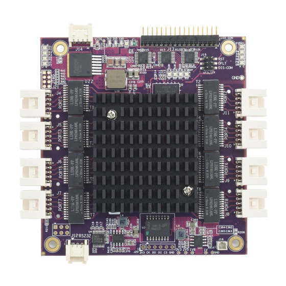
3.2 Board Layout The f ollowing photo shows the locations f or all connectors and jumpers which are described in the next sections. Power In LAN2 LAN1 LAN3 LAN4 LAN5 LAN6 LAN7 LAN8 RS-232 Figure 2. Epsilon-8130 Connectors and Jumpers www.diamondsystems.com Epsilon-8130 User Manual Revision 1.0 PRELIMINARY Page 9... -
Page 10: Connector And Jumper List
4. CONNECTOR AND JUMPER LIST 4.1 Connector and Jumper List The f ollowing table summarizes the f unctions of Epsilon-8130’s interf ace connectors and jumper. Ref er to Figure 2 f or the locations of these connectors on Epsilon-8130. Signal f unctions relating to all of Epsilon-8130’s interf ace connectors are discussed in greater detail in Section 6 of this document. -
Page 11: Connector Pinout And Pin Description
Epsilon-8130 contains eight right-angle, locking pin headers f or the eight Ethernet ports. Each port has the same style and pin out. Each signal is associated with a particular color inside of the Diamond Systems cable part number 6981052. The color coding f or this cable f ollows the TIA/EIA 568B standard. -
Page 12: Led Status Signals (J13)
5.4 LED Status Signals (J13) Connector J13 provides access to the Ethernet LED signals f or each of the eight ports. This connector has duplicate connections f or Reset control input. LEDs may be directly connected to these signals without requiring any current-limiting resistors. -
Page 13: Thermal Solutions
6. THERMAL SOLUTIONS 6.1 Heat Sink Model EPS-8130 contains a heat sink f or cooling. The heat sink is positively af f ixed to the board with 2 screws, and it contains a thermal pad to contact the Ethernet switch IC. The total height conf orms to the height limitations f or a PC/104 f orm f actor board (11.2mm / 0.435”... -
Page 14: Heat Spreader
6.2 Heat Spreader Model EPS-8130-XT contains a heat spreader which serves as both a cooling method and a mounting method f or the board. The heat spreader is the same size as the board and uses a thermal pad to contact the Ethernet switch IC. -
Page 15: Command Line Interface
7. COMMAND LINE INTERFACE The command line interf ace (CLI) is a modal, line-based interf ace with no screen editing f eatures where commands are executed immediately upon end -of -line. The CLI can be accessed directly via the serial connection. The user must log in bef ore CLI commands can be executed. -
Page 16: Help Utility
7.3 Help Utility You may get help by pressing the ? key or entering help. The help inf o depends on the context: • At top level, a list of command groups is displayed. • At group level, a list of the command syntaxes f or the current group is displayed. •... -
Page 17: Mac Commands
(conf ig)# ip http secure-server (conf ig)# ip igmp snooping (conf ig)# ip igmp snooping vlan <v_vlan_list> (conf ig)# ip igmp unknown-f looding (conf ig)# ip route <v_ipv4_addr> <v_ipv4_netmask> <v_ipv4_gw> (conf ig)# ip dhcp retry interf ace vlan <vlan_id> (conf ig)# no ip http secure-redirect (conf ig)# no ip http secure-server (conf ig)# no ip igmp snooping (conf ig)# no ip igmp snooping vlan [ <v_vlan_list>... -
Page 18: Lacp Commands
(conf ig)# dot1x re-authentication (conf ig)# dot1x system-auth-control (conf ig)# dot1x timeout quiet-period <v_10_to_1000000> (conf ig)# dot1x timeout tx-period <v_1_to_65535> (conf ig)# no dot1x authentication timer inactivity (conf ig)# no dot1x authentication timer re-authenticate (conf ig)# no dot1x re-authentication (conf ig)# no dot1x system-auth-control (conf ig)# no dot1x timeout quiet-period (conf ig)# no dot1x timeout tx-period # clear dot1x statistics [ interf ace ( <port_type>... -
Page 19: Spanning-Tree Commands
(conf ig)# logging on (conf ig)# no logging host (conf ig)# no logging on # clear logging [ inf o ] [ warning ] [ error ] [ switch <switch_list> ] # show logging <log_id> [ switch <switch_list> ] # show logging [ inf o ] [ warning ] [ error ] [ switch <switch_list> ] 7.5.10 Spanning-tree Commands (conf ig)# spanning-tree aggregation (conf ig)# spanning-tree edge bpdu-f ilter... -
Page 20: Privilege Commands
(conf ig)# qos storm { unicast | multicast | broadcast } { { <rate> [ kf ps ] } | { 1024 kf ps } } # show qos [ { interf ace [ ( <port_type> [ <port> ] ) ] } | wred | { maps [ dscp -cos ] [ dscp-ingress-translation ] [ dscp-classif y ] [ cos-dscp ] [ dscp-egress-translation ] } | storm | { qce [ <qce>... -
Page 21: Radius Server Commands
(conf ig)# no sntp server # show sntp status 7.5.18 Radius Server Commands (conf ig)# radius-server attribute 32 <id> (conf ig)# radius-server attribute 4 <ipv4> (conf ig)# radius-server deadtime <minutes> (conf ig)# radius-server host <host_name> [ auth-port <auth_port> ] [ acct-port <acct_port>] [ timeout <seconds> ] [ retransmit <retries>... -
Page 22: Firmware Commands
7.5.22 Firmware Commands # f irmware swap # f irmware upgrade <tf tpserver_path_f ile> 7.5.23 Ping Commands # ping ip <v_ip_addr> [ repeat <count> ] [ size <size> ] [ interval <sec onds> ] 7.5.24 Debug Commands (conf ig)# no debug prompt (conf ig)# line { <0~16>... -
Page 23: Examples
7.6 Examples 7.6.1 IP Configuration Below example depicts conf iguration of static IP address, # configure terminal (config)# interface vlan 1 (config-if-vlan)# ip address 192.168.1.60 255.255.0.0 (config-if-vlan)# end Display the IP address to conf irm: # show ip interface brief Vlan Address Method Status... -
Page 24: Snmp Configuration
Virtual LANs (VLANs) are used to divide the network into separate logical areas. VLANs can also be considered as broadcast domains. Following example shows setting up VLAN2 and VLAN3 with switch port mode set to access. #configure terminal (config)# vlan 2 (config)# vlan 3 Set access port, in this case it’s assumed that port 1~3 are connected to PC. -
Page 25: Setup Qos
For debugging network problems or monitoring network traf f ic, the switch system can be conf ig ured to mirror f rame f rom multiple ports to a mirror port. Following example depicts Mirror traf f ic of Port 2 and 3 (Rx) & 4 to 8 (Rx) to Port # configure terminal (config)# monitor destination interface GigabitEthernet 1/1 (config)# monitor source interface GigabitEthernet 1/2-3 rx... -
Page 26: Web Interface
8. WEB INTERFACE The web interf ace of fers an alternate user interf ace to the CLI. The web interf ace is in-band and requires use of one of the Ethernet ports. This port provides simultaneous web management and normal usage. The same commands with the same f unctionality can be accessed via either interf ace. -
Page 27: Port Configuration
8.1.2 Port Configuration Individual ports can be conf igured as f ollows: 1. Connect to the web interf ace of EPS-8130 switch 2. Navigate to Conf iguration -> Ports 3. Each port can be set f or one of the f ollowing conf igurations a. -
Page 28: Change Password
8.1.3 Change Password The switch login password can be changed as f ollows: 1. Connect to the web interf ace of EPS-8130 switch 2. Navigate to Conf iguration -> Security -> Password 3. Enter the Old password and New Password and click on Save (ref er to f igure below) 4. -
Page 29: Set-Up Vlans
8.1.4 Set-up VLANs The f ollowing example shows the conf iguration of a VLAN: 1. Connect to the web interf ace of EPS-8130 switch 2. Navigate to Conf iguration -> VLANS a. In the allowed access VLANs enter number of LANs to be created. In this example 1-3, that creates VLAN2 and VLAN3 b. -
Page 30: Snmp Configuration
8.1.5 SNMP Configuration The f ollowing procedure shows the SNMP conf iguration: 1. Connect to the web interf ace of EPS-8130 switch 2. Navigate to Security -> Switch -> SNMP -> System, and Enable the Mode and set the SNMP version (example: SNMP v1, SNMP v2c &... -
Page 31: Mirroring
3. The trap conf iguration is displayed as f ollows: Enable the Mode and click on Save to save the trap conf iguration. Figure 9 – Trap configuration 8.1.6 Mirroring For debugging network problems or monitoring network traf f ic, the switch system can be conf igured to mirror f rame f rom multiple ports to a mirror port. -
Page 32: Setup Qos
3. Click on Save to save the mirroring conf iguration. Other Mirroring options - Port to mirror also known as the mirror port. Frames f rom ports that have either source (rx) or destination (tx) mirroring enabled are mirrored on this port. Disabled disables mirroring. Mirror Mode Conf iguration 1. -
Page 33: Web Interface Activation / Deactivation
8.1.8 Web Interface Activation / Deactivation The web interf ace can be activated and deactivated through either the command line interf ace or the web Control Panel. Using the Control Panel, in the Conf iguration/Security/Switch/Access Management Conf iguration screen, f irst ensure the mode is set to Disabled as shown below. -
Page 34: Factory Defaults
This copies running-conf ig to startup-conf ig, thereby ensuring that the currently active conf iguration will be used at the next reboot. The f ollowing example shows the Save Startup conf iguration: 1. Connect to the web interf ace of EPS-8130 switch 2. -
Page 35: Physical Reset
8.1.12 Physical Reset A user can load the conf iguration of the switch to f actory defaults using a port loop-back. This also loads the f actory def ault IP conf iguration. This option may be required if the switch IP address is not known and /or the switch is not communicating over the network. -
Page 36: Specifications
9. SPECIFICATIONS The specif ications for Epsilon-8130 are summarized in the f ollowing table. 8-port, layer 2+ switch Ethernet switch Built-in 416MHz MIPs 24KEC microcontroller for configuration and management Number of ports 8 10/100/1000Mbps copper Ethernet ports with non-blocking wire-speed performance 4Mb packet memory On-board memory Shared memory buffer with per=port and CoS memory management... -
Page 37: Appendix Asupported Mibs
APPENDIX A SUPPORTED MIBS Epsilon-8130 supports the f ollowing management inf ormation bases (MIBs). Each MIB contains def initions and inf ormation regarding the properties of managed resources and the services that the agents support. The f ollowing MIBs are supported by Epsilon-8130: •... - Page 38 fis create -b 0x80040000 -r 0 -l 0x40000 -f 0x40000000 -e 0 RedBoot If the above step not showing the f ollowing length incorrect error,skip steps 10-20 and go to step 21. “Image found, but length is incorrect (present image size 0x20000)” 10.
- Page 39 26. Load the f ile Epsilon-8100.gz. load -r -b 0x80040000 -m xmodem 27. From TeraTerm, choose File > Transf er > XMODEM > Send..., select Epsilon-8100.gz, and click Open. 28. Create the managed and managed.bk f ile entries. fis create -r 0x80040000 -e 0x800400bc -l 0x600000 -f 0x401c0000 managed fis create -r 0x80040000 -e 0x800400bc -l 0x600000 -f 0x407c0000 managed.bk Note: File names managed and managed.bk must not be changed.
-
Page 40: Appendix C Changes From Eps-8100 To Eps-8130
APPENDIX C CHANGES FROM EPS-8100 TO EPS-8130 Item Changes Reason for Change EPS-8100 vs EPS-8130 Power section is Changed TPS54540 to LM22679TJE-ADJ/NOPB Updated 3.3V power redesigned f or better Input supply range is same as EPS-8100 (+5V to section manuf acturability +36V) Power section is Updated 2.5V power...
Need help?
Do you have a question about the EPSILON 8130 Series and is the answer not in the manual?
Questions and answers