
Related Manuals for ORTNER GO7 42/42


Summary of Contents for ORTNER GO7 42/42
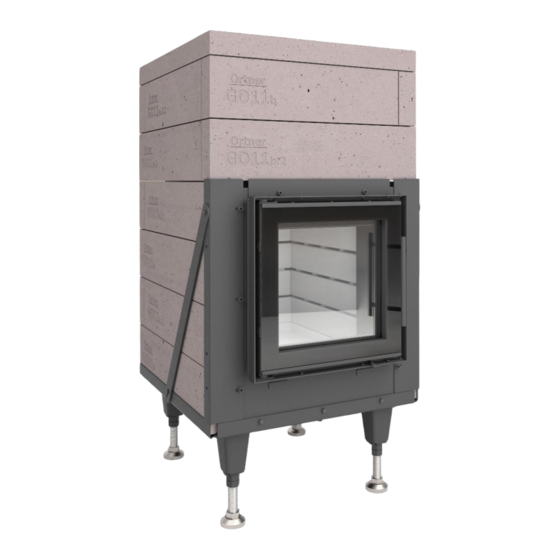
- Page 1 Version: 01 / 2020 Assembly Instructions ORTNER GO7 42/42 Manual and automatic operation...
-
Page 2: Manual And Automatic Operation
Ortner GO7 42/42 Manual and automatic operation Version: 01 / 2020 Because the position of the burn-out from the combustion chamber can be determined individually, a length adjustment may be necessary with some components! (Details are provided in the document.) A sufficient quantity of combustion air must be provided (calculation is required). -
Page 3: Table Of Contents
Content Technical specifications Important information before the installation Initial steps Outlet to the side or back Outlet to the side or back Outlet top Technical dimensioned drawing General information Fire and heat protection General: Mounting surfaces TO BE PROTECTED Mounting surfaces NOT TO BE PROTECTED General Schematic sketch Exploded view... -
Page 4: Technical Specifications
The following materials are required for the assembly of the Ortner storage front • Fibre mat strips (for sealing between the ceramic and the metal parts), included in the delivery • Bedding mortar HK for the bonding of the combustion chamber jacket, included in the delivery •... -
Page 5: Important Information Before The Installation
Check all screws on the frame and retighten, if necessary. • Shell components (red) must always be made gastight with Ortner bedding mortar HK. • Depending on the specific burn-out situation, certain shell components must be cut to length accordingly. -
Page 6: Initial Steps
Initial steps Outlet to the side or back Adjust Adjust mantle block mantle block The outlet brick (GOA.1) is always located in the top 3 rows. GOA.1 GOA.1 With the outlet positioned on the right / rear right, the long brick is located in the bottom row on the right-hand side. -
Page 7: Outlet Top
Outlet top Set up the base frame, level the bottom part and if necessary, connect the aluminium flexible hose for the combustion air supply. Loosen the screws of the metal strips on the Loosen the frame (contact surface with jacket screws components) and on the tabs on the base frame. - Page 8 First position the 1st row of the jacket parts dry on the fibre pads in the base frame. The first row is only bonded at the front sides towards each other using bedding mortar HK. Now press the bottom clamping strip GO7a GO11b against the jacket bricks and secure these...
- Page 9 Place the base plates and the ash bricks in the combustion chamber (do not bond!) Insert the first two rows of GOS in the combustion chamber. No bond is created in the course of this. GOS5 GOS7 The designation of the bricks relates to the number of segments.
- Page 10 GOS5 GOS7 OPEN JOINT Now install the remaining rows of the GOS. GOS6 In the course of this, in places a 6 mm air GOS7-1 gap must be created between the bricks. GOS7 Caution: The GOS without nubs must be GOS5 GOS5 placed in the top row.
- Page 11 Position the deflection plate on the GOS and always slide this to the very back and to the side of the burn-out. GO1.5.2 GO1.5 GO1.5.2 Now position the cover of the post- combustion chamber.
- Page 12 GOA.5 GOA.4 Bond the cover of the jacket with the side parts. Use ORTNER bedding mortar HK for this task. Caution: The minimum distance between the cover of the post-combustion chamber and the jacket cover must be at least 12 mm.
-
Page 13: Technical Dimensioned Drawing
Technical dimensioned drawing (applies to both automatic as well as manual operation) -
Page 14: General Information
• The GO7 42/42 may not be operated in installation spaces that are ventilated by means of fans in ventilation or heating air systems with the exception that the safe operation of the stove can be ensured. This means: A simultaneous operation of an air extraction system and the firing installation must be prevented. -
Page 15: Fire And Heat Protection
In the event of the use of Ortner Isoboard: 10 cm brick lining + 9 cm Ortner Isoboard. Or 3 cm Isoboard at the mounting wall + active back ventilation (at least 5 cm gap width) + 6 cm Ortner Isoboard (towards the stove, with offset joints). -
Page 16: General
General When using substitute insulation materials, these may only be processed with processing media in accordance with the specifications of the officially recognised suitability certificate (applies to Germany). When dimensionally stable substitute insulation materials are used without brick lining, then these boards must be constructed with at least two layers. -
Page 17: Schematic Sketch
Schematic sketch... - Page 18 10) Insulation of the floor: In the event that the installation surface is stable, however made of combustible components, then floor insulation must be created. This can be performed with the use of a reference or substitute insulation material. In the event of the use of Ortner Isoboard, this corresponds to a layer thickness of 6 cm.
-
Page 19: Exploded View
Exploded view...
Need help?
Do you have a question about the GO7 42/42 and is the answer not in the manual?
Questions and answers