Advertisement
Quick Links
Advertisement

Subscribe to Our Youtube Channel
Related Manuals for Juniper AP64


Summary of Contents for Juniper AP64
- Page 1 Juniper AP64 Access Point Deployment Guide Published 2024-07-19...
- Page 2 The Juniper Networks product that is the subject of this technical documentation consists of (or is intended for use with) Juniper Networks software. Use of such software is subject to the terms and conditions of the End User License Agreement ("EULA") posted at https:/ /support.juniper.net/support/eula/.
-
Page 3: Table Of Contents
Mounting Brackets for AP64 | 9 Connect the Grounding Cable | 13 Mount the AP64 on a Wall Using APOUTBR-FM (Flush Mount) | 13 Mount the AP64 on a Pole Using APOUTBR-FM (Flush Mount) | 14 Mount the AP64 on a Wall Using APOUTBR-FM2 (Flush Mount) | 16... -
Page 4: About This Guide
About This Guide Use this guide to install, manage, and troubleshoot the Juniper® AP64 High-Performance Access Point. After completing the installation procedures covered in this guide, refer to the Juniper Mist™ Wi-Fi Assurance documentation for information about further configuration. -
Page 5: Overview
C HAPTER Overview AP64 Access Point Overview | 2 AP64 Components and Specifications | 4 Power-On Options for the AP64 | 6... -
Page 6: Ap64 Access Point Overview
The AP64 can operate in either multi-user or single-user mode. The AP64 is backward compatible with the 802.11a, 802.11b, 802.11g, 802.11n, and 802.11ac wireless standards. The AP64 provides maximum data rates of 2400 Mbps in the 6-GHz band, 1200 Mbps in the 5-GHz band, and 575 Mbps in the 2.4-GHz band. - Page 7 Internal Outside of the United States NOTE: Juniper products are manufactured in accordance with electrical and environmental regulations specific to certain regions and countries. Customers are responsible for ensuring that any regional or country-specific SKUs are used only in the specified authorized area. Failure to do...
-
Page 8: Ap64 Components And Specifications
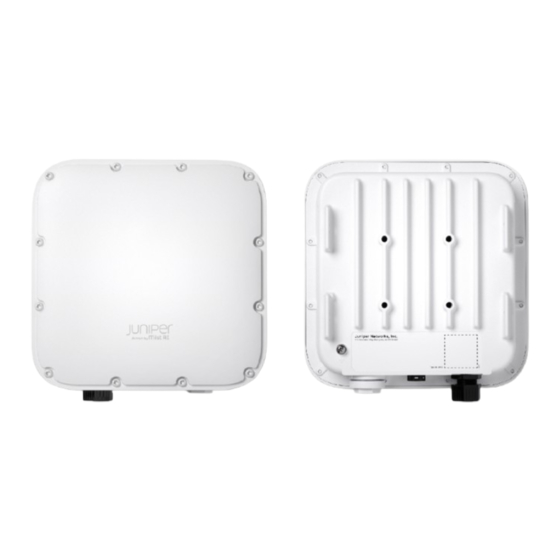
Marvis can identify issues such as offline APs and APs with insufficient capacities and coverage issues. • Automatic RF optimization—Juniper radio resource management (RRM) automates dynamic channel and power assignment, which helps reduce interference and enhance user experience. Mist AI monitors the coverage and capacity metrics to optimize the RF environment. - Page 9 A multicolor status LED to indicate the status of the AP and to help troubleshoot issues. See Troubleshoot a Juniper Access Point The AP64 also has a grounding point on the rear. Figure 3 on page 6 shows the location of the grounding point on the AP64.
-
Page 10: Power-On Options For The Ap64
Figure 3: Rear Panel of AP64 For AP64 specifications, see the AP64 Datasheet. Power-On Options for the AP64 You can use any of the following options to power on the AP: • Power over Ethernet plus (PoE+) from an Ethernet switch We recommend that you use an Ethernet cable with a maximum length of 100 m to connect the access point (AP) to the switch port. - Page 11 AP might power up, but the Ethernet link does not transmit data across such a long cable. You might see the status LED blink yellow twice indicating that the AP is unable to receive data from the switch. • PoE injector PoE Requirements for Juniper Mist APs for the power requirements for an AP64.
-
Page 12: Installation
C HAPTER Installation Mount the AP64 Access Point | 9 Connect an AP64 to the Network and Power It On | 28... -
Page 13: Mount The Ap64 Access Point
Mount the AP64 on a Pole (Articulating Mount) | 22 Connect an RJ-45 Cable Gland | 25 You can mount the AP64 either on a wall or on a pole using two methods—flush mount or articulating mount. Mounting Brackets for AP64... -
Page 14: Mounting Brackets For Flush Mount Method
Table 2: Part Numbers for AP64 Mounting Brackets Part Number Description APOUTBR-FM Flush mount brackets APOUTBR-FM2 Flush mount brackets (new) APOUTBR-ART2 Articulating mount brackets Mounting Brackets for Flush Mount Method The mounting accessories for flush mounting include the following: • One flush mount bracket (part number: APOUTBR-FM) •... -
Page 15: Mounting Brackets For New Flush Mount Method
Figure 4: APOUTBR-FM Flush Mount Bracket 1—Screw holes to use for mounting an AP63 on a wall 2—Holes to use for attaching hose clamps 3—Screw holes to use for attaching the bracket to an AP63 Mounting Brackets for New Flush Mount Method The mounting accessories for flush mounting include the following: •... -
Page 16: Mounting Brackets For Articulating Mount Method
• Four sets of M6 screws, washers, and lock washers • Five sets of anchors and screws Mounting Brackets for Articulating Mount Method The mounting accessories for articulating mounting include the following: • Three mounting brackets (part number: APOUTBR-ART2): • Mounting bracket 1 •... -
Page 17: Connect The Grounding Cable
• Four bolts and nuts Connect the Grounding Cable We recommend that you ground the AP before mounting it on a wall or pole. The AP64 has a single- hole protective grounding terminal on the rear. Use this grounding terminal to ground the AP. -
Page 18: Mount The Ap64 On A Pole Using Apoutbr-Fm (Flush Mount)
Figure 5: Attach the APOUTBR-FM Flush Mount Bracket to an AP64 4. Position the AP such that the two screws that you inserted in Step 1 fit into the holes in the bracket. Slide the AP downward so that the screws lock in place. - Page 19 2. Attach the APOUTBR-FM flush mount bracket to the AP by using the four screws, washers, and lock washers provided along with the AP. Figure 8: Attach the APOUTBR-FM Flush Mount Bracket to an AP64 3. Mount the AP on the pole. Wind the open end of the hose clamps around the pole and tighten the hose clamp screws by using a screwdriver.
-
Page 20: Mount The Ap64 On A Wall Using Apoutbr-Fm2 (Flush Mount)
Figure 9: Mount an AP64 on a Pole (Flush Mount) Mount the AP64 on a Wall Using APOUTBR-FM2 (Flush Mount) To flush mount the AP64 on a wall: 1. Drill four holes on the wall based on the location of holes in the APOUTBR-FM2 mounting bracket. -
Page 21: Mount The Ap64 On A Pole Using Apoutbr-Fm2 (Flush Mount)
Figure 11: Attach the AP64 to the APOUTBR-FM2 4. Secure the AP64 by using the four M6 screws, washers, and lock washers provided along with the Figure 12: Mount the AP64 on a Wall (Flush Mount) Mount the AP64 on a Pole Using APOUTBR-FM2 (Flush Mount) To flush mount the AP64 on a pole: 1. - Page 22 Tighten the screws until the mounting bracket is secured in place. Figure 14: Install the APOUTBR-FM2 3. Attach the AP64 to the APOUTBR-FM2 mounting bracket using the four M6 screws, washers, and lock washers provided along with the AP.
-
Page 23: Mount The Ap64 On A Wall (Articulating Mount)
Figure 15: Mount an AP64 on a Pole (Flush Mount) Mount the AP64 on a Wall (Articulating Mount) To mount the AP64 on a wall using the articulating mount bracket: 1. Disassemble the APOUTBR-ART2 mounting bracket 1 by removing the two screws. - Page 24 Figure 18 on page Figure 18: Attach the APOUTBR-ART2 Mounting Bracket 2 to the Mounting Bracket 1 4. Attach the APOUTBR-ART2 mounting bracket 3 to the AP64 by using the four M6 screws, washers, and lock washers provided along with the AP.
- Page 25 Figure 19: Attach the APOUTBR-ART2 Mounting Bracket 3 to the AP64 5. Attach the APOUTBR-ART2 mounting bracket 2 to the mounting bracket 3 by using two bolts and nuts.
-
Page 26: Mount The Ap64 On A Pole (Articulating Mount)
Figure 20: Mount the AP64 on a Wall (Articulating Mount) Mount the AP64 on a Pole (Articulating Mount) To mount the AP64 on a wall using the articulating mount bracket: 1. Attach the hose clamps to the APOUTBR-ART2 mounting bracket 1. Use a screwdriver to release the hose clamps and then pass the hose clamps through the slots on the bracket. - Page 27 Figure 21: Attach the APOUTBR-ART2 Mounting Bracket 1 to a Pole 3. Attach the APOUTBR-ART2 mounting bracket 2 to the mounting bracket 1 by using two bolts and nuts included in the bracket kit. Orient the side with the label ← UP → as shown in Figure 22 on page Figure 22: Attach the APOUTBR-ART2 Mounting Bracket 2 to the Mounting Bracket 1...
- Page 28 4. Attach the APOUTBR-ART2 mounting bracket 3 to the AP64 by using the four M6 screws, washers, and lock washers provided along with the AP. Figure 23: Attach the APOUTBR-ART2 Mounting Bracket 3 to the AP64 5. Attach the APOUTBR-ART2 mounting bracket 2 to the mounting bracket 3 by using two bolts and...
-
Page 29: Connect An Rj-45 Cable Gland
Figure 24: Mount the AP64 on a Pole (Articulating Mount) Connect an RJ-45 Cable Gland Use an RJ-45 cable gland when you connect an RJ-45 cable to the AP. The cable gland helps secure the RJ-45 cable and protects the cable from damage. To connect an RJ-45 cable using the cable gland: 1. - Page 30 Figure 25: Disassemble an RJ-45 Cable Gland 2. Insert the RJ-45 cable through the cable gland: a. Open the seal and insert the RJ-45 cable through the nut and the seal. Figure 26: Insert the RJ-45 Cable Through the Nut and the Seal of the Cable Gland b.
- Page 31 3. Connect the RJ-45 cable to the AP port. Attach the cable gland to the AP and tighten it with a torque of 10–12 kg-cm. Then, fully tighten the nut to the cable gland with a torque of 7–10 kg-cm. Figure 28: Attach a Cable Gland to the AP64...
-
Page 32: Connect An Ap64 To The Network And Power It On
• The Mist cloud then provisions the AP by pushing the required configuration after the AP is assigned to a site. To ensure that your AP has access to the Juniper Mist cloud, ensure that the required ports on your Internet firewall are open. See Firewall Configuration. - Page 33 • We recommend that you avoid using a static IP address on an AP. The AP uses the configured static information whenever it reboots, and you cannot reconfigure the AP until it connects to the network. If you need to correct the IP address, you'll need to reset the AP to the factory-default configuration. If you must use a static IP address, we recommend that you use a DHCP IP address during the initial setup.
-
Page 34: Troubleshoot
C HAPTER Troubleshoot Contact Customer Support | 31... -
Page 35: Contact Customer Support
If you are unable to resolve the issue, you can create a support ticket on the Juniper Mist portal. The Juniper Mist Support team will contact you to help resolve your problem. If needed, you can request a Return Material Authorization (RMA). - Page 36 4. Select the appropriate ticket type depending on the severity of your problem. NOTE: Selecting Questions/Other will open a search box and redirect you to available documentation and resources related to your issue. If you cannot resolve your issue by using the suggested resources, click I still need to create a ticket.
- Page 37 • The system logs from the device NOTE: To share device logs: a. Navigate to the Access Points page in the Juniper Mist portal. Click the impacted device. b. Select Utilities > Send AP Log to Mist in the top right corner of the device page.
Need help?
Do you have a question about the AP64 and is the answer not in the manual?
Questions and answers