Table of Contents
Advertisement
Quick Links
PAT Hirschmann DS85 Service Manual
The PAT Hirschmann DS85 Service Manual provides detailed instructions and guidance for
maintaining and troubleshooting the DS85 Load Moment Indicator (LMI) system, a vital
safety feature for crane operations. The DS85 LMI system warns operators of potential
overloads and unsafe lifting conditions, enhancing overall crane safety. The manual covers
a broad range of topics, from system components and operation principles to specific
maintenance procedures and troubleshooting techniques.
MORE INFORMATION HERE
https://store.bodetechnicalservices.com/products/pat-ds85-console
DS85 System Overview
The DS85 system is a CAN-bus-based system that integrates several components,
including a central processing unit, pressure transducers, angle sensors, length sensors,
and anti-two-block (A2B) devices. The central unit monitors and processes data from the
sensors, providing real-time feedback on crane load and movement. This feedback is
essential for preventing overloads by stopping certain crane functions if preset load limits
are exceeded. The system stores crane-specific data, such as load charts and boom
dimensions, in the central processor, which it uses to make calculations based on the
actual operating conditions.
System Components
1. Operating Console: Displays information on load, boom angle, length, and crane status.
It includes LEDs for operational warnings and an alarm system.
2. Pressure Transducers: Measure hydraulic pressure in the lift cylinder, providing data on
crane load conditions.
3. Angle and Length Sensors: Track boom angle and length through a potentiometer
system, delivering precise position data to the console.
Advertisement
Table of Contents

Subscribe to Our Youtube Channel
Related Manuals for PAT Hirschmann DS85


Summary of Contents for PAT Hirschmann DS85
- Page 1 PAT Hirschmann DS85 Service Manual The PAT Hirschmann DS85 Service Manual provides detailed instructions and guidance for maintaining and troubleshooting the DS85 Load Moment Indicator (LMI) system, a vital safety feature for crane operations. The DS85 LMI system warns operators of potential overloads and unsafe lifting conditions, enhancing overall crane safety.
- Page 2 4. A2B System: Includes transmitters and receivers that prevent the hook block from hitting the boom, signaling the operator with alarms and locking out certain functions if necessary. Hirschmann DS85 Key Theories The manual includes detailed explanations on the theories of angle, length, and pressure measurement: - Angle Theory: The angle sensor operates through a potentiometer driven by a weighted pendulum, transmitting data digitally via the CAN-bus.
- Page 3 This manual is an invaluable resource for maintenance personnel, outlining everything from installation and component identification to advanced troubleshooting techniques. By following the guidance in this manual, users can ensure that the DS85 LMI system functions correctly, enhancing crane safety and preventing equipment damage. MORE INFORMATION HERE: https://store.bodetechnicalservices.com/products/pat-ds85-console...
-
Page 4: Load Moment Indicator
HIRSCHMANN www.patamerica.com LOAD MOMENT INDICATOR DS 85/0002 central unit/ console SERVICE MANUAL P/N 031-300-190-166 REV G 10/05/2015... - Page 5 Service Manual DS 85 NOTICE Hirschmann makes no warranty of any kind with regard to this material, including, but not limited to, the implied warranties of merchantability and/or its fitness for a particular purpose. Hirschmann will not be liable for errors contained in this manual or for incidental or consequential damages in connection with the furnishing, performance, or use of this manual.
-
Page 6: Table Of Contents
Service Manual DS 85 TABLE OF CONTENTS GENERAL INFORMATION ....................1 WARNINGS ........................1 SYSTEM DESCRIPTION ....................2 ..............3 ESCRIPTION OF THE YSTEM OMPONENTS FREQUENTLY ASKED QUESTIONS: ................5 ANGLE THEORY ....................... 6 LENGTH THEORY ......................9 ..........11 ABLE ENGTH ABLE EPLACEMENT... - Page 7 Service Manual DS 85 TROUBLESHOOTING MOISTURE ................53 19.1 ......................53 ATER NGRESS 19.2 ......................54 ONDENSATION © Hirschmann Rev.G 10/05/15 190166_G.DOCXG...
-
Page 8: General Information
1 GENERAL INFORMATION This service manual is designed to assist a service or maintenance person in identifying system problem areas or malfunctions. A digital voltmeter with the capability to measure current will be required, along with standard maintenance and service tools. NOTE: Knowledge of how to use a voltmeter to measure both voltage and current is assumed. -
Page 9: System Description
The length sensor/cable reel is mounted inside the base which measures the boom length. The PAT RATB works like our normal Anti-Two-Block. It alerts to an impending two-block condition. This alert can come in the form of an audible alarm and visual LED or with the optional function lockout if the crane is so equipped. -
Page 10: Description Of The System Components
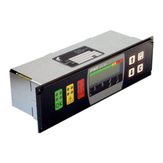
DESCRIPTION OF THE SYSTEM COMPONENTS Fig. 1: Components of the LMI system PAT DS 85 SLIP RING FROM UPPER LOWER WILL BE ONE OF THESE TWO PLACES 1 Operating W BATT B ALAR POWE 2 Pressure Console RATB RECEIVER 031-300-050-... - Page 11 Service Manual DS 85 Central Unit/Console: Inside the console there is a CPU and connection board. The board has a hard mounted connector for power, ground, bus controller, and slew indication. Displays all geometrical information such as actual load, maximum load permitted by load chart, working radius, and length, angle, and head height of main boom.
-
Page 12: Frequently Asked Questions
So, what’s wrong? Assuming you are reading these pages because of some kind of problem with the PAT system, let us try to guide you quickly to solving the problem. In most cases, your problem will fall under the following categories: ... -
Page 13: Angle Theory
Service Manual DS 85 5 ANGLE THEORY The System measures the angle of the main boom of the machine with an angle sensor. The angle sensor is contained within the angle sensor box (Radio A2B option) or within the Cable Reel (Hardwired A2B option) located on the left side of the main boom. - Page 14 (length) (angle) CAN-Bus electronics in angle sensor box. (CAN) (A2B) (length) (angle) CAN-Bus electronics in cable reel. The angle sensor has a potentiometer built in that is driven by a pendulum. As the angle changes, so will the pendulum and with it the potentiometer’s axle. The converter board supplies a constant voltage of 5V to the angle sensor and in return monitors the voltage of the potentiometer.
- Page 15 Service Manual DS 85 The angle sensor returns a voltage between 1.875V at 90 degrees and 3.125V at 0 degrees: Angle Sensor Signal on Pin 3 Angle Voltage 1.875 2.083 2.292 2.500 2.708 2.917 3.125 Note: Actual voltages will vary slightly. Measure this voltage between Pin 5 (GND) and Pin 3 of Terminal X21.
-
Page 16: Length Theory
6 LENGTH THEORY The system measures the length of the main boom of the machine with a length sensor. The length sensor is contained within the cable reel, located in the base of the main boom. Block Diagram Radio A2B Option: Length CAN-Bus DS 85... - Page 17 Service Manual DS 85 Terminal X20 + (~ 4.8V) Signal - (~ 0.2V) Verify that the sensor is being supplied with about 4.7V by measuring between pin 5 (-) and Pin 1 (+) of terminal X20. If the voltage is outside of a range of 4.5 to 5 V, the converter board might be defective.
-
Page 18: Cable Reel Length Cable Replacement Procedure
CABLE REEL LENGTH CABLE REPLACEMENT PROCEDURE Replace length cable using the following procedure: Refer to system electrical wiring diagram and cable reel - parts list 1. Remove cable reel and guide from mounting brackets. 2. Remove old length cable from cable drum and machine. 3. -
Page 19: Cable Reel Replacement Procedure
Service Manual DS 85 CABLE REEL REPLACEMENT PROCEDURE Replace cable reel using the following procedure: Refer to system electrical wiring diagram and cable reel - parts list 1. Remove cable reel and guide from mounting brackets. 2. Remove cover from cable reel. 3. -
Page 20: Lwg Cable Reel Length/Angle Sensor Replacement Procedure
LWG CABLE REEL LENGTH/ANGLE SENSOR REPLACEMENT PROCEDURE MOUNTING Mount cable reel on cab side of boom to ensure adequate visibility. Length cable should spool from the top of the drum. NOTE: Boom with a flat side: Use four (4) 2-inch hook bolts. Trapezoidal Boom with a slanted side: Use two (2) 2-inch and two (2) 4-inch hook bolts. - Page 21 Service Manual DS 85 CALIBRATION 1. After installation, remove cover from cable reel. With the boom full retracted and boom stops disengaged (if applicable), adjust the length potentiometer by turning the screw in the center of the large nylon gear on the length sensor counter-clockwise until a soft stop occurs, and reinstall the cover on the reel.
-
Page 22: Pressure Theory
7 PRESSURE THEORY The System measures the pressure of the boom lift cylinder for both rod- and piston-side. Both sensors are contained within one box that also contains the electronics needed for amplification and creation of the CAN-Bus signal. Block Diagram: Pressure- CAN-Bus DS 85... -
Page 23: Load Theory
Service Manual DS 85 8 LOAD THEORY Please note that the load displayed by the LMI is not a direct measurement, but a calculated value that is based on a lot of factors. Outside of the measured values (sensors), those include: ... - Page 24 There are 6 LEDs on the front panel of the device, which indicate the status of various operating conditions. The meaning of the signals can be taken from the table: off: lights: flashes slowly: flashes rapidly: No supply Supply voltage is voltage present present...
- Page 25 Service Manual DS 85 Which does it mean when the ‘Low Batt’ LED lights up? If a ‘Low Battery’ LED lights up, this means that the battery set in the respective wireless sensor is exhausted (remaining capacity < 6,5 %) and must be replaced as soon as possible. What does it mean when the ‘Info’...
-
Page 26: A2B Problem - Hardwired A2B Option
10 A2B PROBLEM – HARDWIRED A2B OPTION © Hirschmann Rev. G 10/05/15 190166_G.DOCXG... -
Page 27: Console Display
Service Manual DS 85 CONSOLE DISPLAY If the console is not showing any lights, such as warning lights, backlighting, etc. it is most likely missing power. Start with the following: Warning Lights Backlighting Check if power is being supplied to the console/central unit. Measure on the 16 socket connector. Pin 1 is +Ub (12V), Pin 3 is GND. -
Page 28: Anti-Two Block System Setup
12 ANTI-TWO BLOCK SYSTEM SETUP 12.1 SETUP OVERVIEW The PAT RATB is easily configured to communicate with up to 2 transmitters. Simply by depressing the red programming button for several seconds, the receiver can sense the transmitters being used and auto-configure to communicate with those transmitters. - Page 29 Service Manual DS 85 © Hirschmann Rev.G 10/05/15 190166_G.DOCXG...
- Page 30 © Hirschmann Rev. G 10/05/15 190166_G.DOCXG...
-
Page 31: Deleting Devices
Service Manual DS 85 12.3 DELETING DEVICES Wireless hoist limit switches that are being decommissioned must be deleted and deactivated by first removing the batteries. Follow the procedure described below to delete a wireless hoist limit switch. Open the housing of the iFLEX TRS 12 as described previously. ▲... - Page 32 Install four fresh batteries into the proper location and direction as indicated on the battery holder. Make sure that the cardboard tube is installed as shown. Observe the LED on the underside of the housing. This should light up with short pulses. Reinstall the cover of the battery compartment.
-
Page 33: Can-Bus Communication
Service Manual DS 85 13 CAN-BUS COMMUNICATION BRIEF DESCRIPTION OF A CAN BUS SYSTEM CAN stands for “Controller Area Network”. Its intended use is as a serial bus system for a network of controllers. Each controller connected through a CAN chip is called a "node" and is mostly used to acquire data from a sensor. - Page 34 So, what do you do when you are having a problem with one of those codes? In case of an E61, start by checking your cabling. You can verify that power is being supplied to the sensor by testing the CAN connectors per this layout: Connector M12, 5 contacts Pin Layout (CiA DR-303-1 7.2)
- Page 35 Service Manual DS 85 E64 In case of an E64, the CU is reporting no signal from the CAN-Bus converter board in the angle sensor box. Start by checking your cabling between pressure transducer and cable reel. You can verify that power is being supplied to the sensor by testing the CAN connectors per the above pin layout or by opening up the angle sensor box (remove the lid) and making sure the red LED on the board is blinking.
- Page 36 Please refer to table below for more values. Voltage Values displayed [mV] +/- 10mV Value displayed Value Pressure Transducers 300 bar, type 314 1500 1088 2500 2176 3500 3263 4500 4351 Angle Sensor degrees boom vertical 1500 67.5 2500 3500 22.5 4500 boom horizontal...
- Page 37 Service Manual DS 85 Connect the two cables on the Transducer block together. Replace transducer block. Ohm the cable from the pressure transducer block to the length/angle sensor or angle sensor box. Cable checks good Replace Check connector at angle the cable.
-
Page 38: Troubleshooting A Sensor Problem Using The Display
14 TROUBLESHOOTING A SENSOR PROBLEM USING THE DISPLAY To determine whether there is a problem with a sensor, the system has “sensor output screen” built in to make trouble-shooting easier. This is the right place to start if you are suspecting a problem with a sensor (and you don’t have an error code displayed). -
Page 39: Drawings
Service Manual DS 85 15 DRAWINGS 15.1 CONSOLE/CENTRAL UNIT TO CRANE WIRING DIAGRAM © Hirschmann Rev.G 10/05/15 190166_G.DOCXG... -
Page 40: Length/Angle Sensor Wiring Diagram
15.2 LENGTH/ANGLE SENSOR WIRING DIAGRAM © Hirschmann Rev. G 10/05/15 190166_G.DOCXG... -
Page 41: Hardwired A2B Wiring Diagram
Service Manual DS 85 15.3 HARDWIRED A2B WIRING DIAGRAM © Hirschmann Rev.G 10/05/15 190166_G.DOCXG... - Page 42 © Hirschmann Rev. G 10/05/15 190166_G.DOCXG...
-
Page 43: Spare Part Listings
Service Manual DS 85 16 SPARE PART LISTINGS 16.1 CONSOLE/CENTRAL UNIT PART NO. 031-300-060-455 PART NO. DESCRIPTION 024-085-100-002 FRONTFACE, PREASSEMBLED 024-000-050-002 HOUSING, DS85 024-000-100-095 CENTRAL UNIT ACCY, MEMBRANE VENT, PG11 024-050-300-101 MAINBOARD, CAN w/o FLASH E-EPROM 024-050-300-106 CONNECTION BOARD 031-300-050-223 FUSE, 2 AMP 024-050-300-110 KEYBOARD... -
Page 44: Pressure Transducer Block
Power Cable assembly (wiring harness) CAN bus from console (90° connector) to pressure PART NO. 031-300-060-443 transducer block PART NO. 031-300-060-453 CAN bus from pressure transducer to angle sensor box (see below) PART NO. 10968 16.2 PRESSURE TRANSDUCER BLOCK DAV314/0014 PART NO. 044-314-060-014 Piston Side Rod Side Cutting ring for pressure transducers PART NO. -
Page 45: Angle Sensor Box
Service Manual DS 85 16.3 ANGLE SENSOR BOX PART NO. 031-300-060-437 PART NO. DESCRIPTION 064-143-060-009 SENSOR, ANGLE WG143/9 iFLEX CAN 068-000-300-103 CAN-BUS CONVERTER BOARD 10-30V 932321100 CONNECTOR, PANEL MOUNT SOCKET 3 + PE 092-000-060-387 CONNECTOR, BRAD HARRISON 5-PIN RECPT. MALE 092-000-060-382 CABLE, 3POL JST-PLUG 15cm ©... -
Page 46: Cable Reel Assembly
16.4 CABLE REEL ASSEMBLY PART NO. 060826 PART NO. DESCRIPTION HARDWARE, DRUM (FACTORY SERVICEABLE) 031-300-050-131 BRACKET, LG105 WITH CABLE GUIDE 031-300-060-374 CABLE ASSY, 15’ (3 COND. WITH 4 PIN PLUG) 060831 CABLE ASSY, LENGTH (35’) w/ RING TERMINAL & CLAMP 024-441-060-409 STRAIN RELIEF, PG9 4-6mm YELLOW/WHITE 031-300-060-682... -
Page 47: Cable Reel Assembly
Service Manual DS 85 16.5 CABLE REEL ASSEMBLY LWG508 PART NO. 068-508-060-001 © Hirschmann Rev.G 10/05/15 190166_G.DOCXG... -
Page 48: Radio A2B
16.6 RADIO A2B 060864 - Wireless Receiver TRS12 060741 - Wireless A2B Transmitter Assembly (PATB5 2.4GHz) (PATB5 2.4GHz) 031-300-050-536 Card board tube 031-002-060-022 Radio A2B switch 031-300-050-276 A2B Mounting standoff 031-300-050-264 A2B mounting plate 031-300-210-012 Weight and chain 031-300-100-037 Chain connector, quick link 031-300-050-272 Lynch pin 031-300-050-537 Transmitter Battery Cover 031-300-050-768 Antenna... -
Page 49: Service Screen For Sensor Calibration
Service Manual DS 85 17 SERVICE SCREEN FOR SENSOR CALIBRATION 17.1 ACTIVATING THE SERVICE SCREEN FOR SENSOR CALIBRATION Enter the calibrate sensors menu by using the following procedure: To start function press CALIB. SENSORS ▓ Press to calibrate sensors. SENSOR OUTPUTS USER No. -
Page 50: Calibrate Length Input
When the boom is in the rest position bleed to continue, BOOM DOWN COMPL DISCONNECT HYDR press Press to continue. DISCONNECT HYDR Press to continue. ▓ EXIT Press to calibrate. Check the sensor outputs screen to check the zero point. At the zero point, the millivolt should be 0500 ±20mV. -
Page 51: Calibrate Angle Input
Service Manual DS 85 Check the sensor outputs screen retracted and extended lengths. Retracted length should be correct at 0500mV and extended boom length will depend on the model. 0502mV 2025mV Extended main boom , millivolts 30.6 f t 55.7° 17.4 CALIBRATE ANGLE INPUT The angle sensor is calibrated at four different reference angles of approximately 0°, 40°, 60°, and... - Page 52 BOOM T 40.3 keys to change CHANGE angle to match the BOOM T CHANG 40.0 angle. Press to calibrate the main boom angle. Move boom so the CHANGE angle is with in ±2° of the BOOM T angle. to BOOM T 65.6 40.3 continue, press.
- Page 53 Service Manual DS 85 Using a calibrated inclinometer placed flat on the main boom, verify that the indicated boom angle matches the measured boom angle within +/- 0.2 degrees. Check the sensor outputs screen for 0°, 45°, 60°, and 70° 0502mV 2025mV 30.6 f t...
-
Page 54: Error Codes
18 ERROR CODES The following Error Code Table gives a brief description of Error Codes elimination. Refer to the noted sections for detailed Troubleshooting information. Error Code Error Possible Cause Elimination Fallen below radius Fallen below the Luff down the boom to a range or angle range minimum radius or gone radius or angle specified in... - Page 55 Service Manual DS 85 Error Code Error Possible Cause Elimination Fallen below lower Length potentiometer is Replace length limit value for potentiometer, see defective measuring channel section Length Sensing "length main boom" Pressure transducer is Replace pressure Fallen below the lower limit value in defective.
- Page 56 Error Code Error Possible Cause Elimination Upper limit value in refer to E12 refer to E12 measuring channel “pressure piston side” has been exceeded refer to E12 refer to E12 Upper limit value in measuring channel “pressure rod side”...
- Page 57 Service Manual DS 85 Error Code Error Possible Cause Elimination Error in the Write/read memory Replace central unit write/read memory, (RAM) or central unit (RAM) defective. Error in the The CRC sign of the Restart the LMI monitored write/ monitored write/read read memory.
- Page 58 Error Code Error Possible Cause Elimination Can bus port in the Replace the central unit central unit defective Blown fuse in console Replace 2 amp fuse Cable between the Check the cable to the Error in the can bus data transfer of the central unit and the...
- Page 59 No valid A2B switch status CAN bus delay Replace cable to the A2B switch Note: If an error message is displayed which is not contained in above list, please contact the PAT service department. © Hirschmann Rev.G 10/05/15 190166_G.DOCXG...
-
Page 60: Troubleshooting Moisture
1) Spray Cleaning The enclosures used for the PAT LMI system are water protected to IP 65. This means protection against the environment, such as rain. However, through the use of spray cleaner at short distances, it is possible to force water through the gasket or strain relieves. - Page 61 If the internal wires turn with the outer cable, the strain relief is loose. Get a new grommet (insert) through your PAT representative and replace the existing one with the new one. Tighten the strain relief correctly. Note: Whenever a strain relief is opened, i.e.
Need help?
Do you have a question about the Hirschmann DS85 and is the answer not in the manual?
Questions and answers