
Related Manuals for PAT DS 350 / 1334 GRAPHIC


Summary of Contents for PAT DS 350 / 1334 GRAPHIC
- Page 1 LOAD MOMENT INDICATOR DS 350 / 1334 GRAPHIC RCL for Lattice Boom Truck Cranes OPERATOR'S MANUAL P/N L-B H9L0021 / PAT 031-300-190-088, Rev. -, 09/15/2000...
-
Page 3: Table Of Contents
Operator's Manual DS 350 / 1334 TABLE OF CONTENTS GENERAL INFORMATION ..................1 WARNINGS ......................1 SYSTEM DESCRIPTION ..................2 YSTEM UNCTION ..........................PERATING ONSOLE ........................... LC D ISPLAY ............................ONTROL DENTIFICATION ........................CONFIGURATION SETUP ..................10 RCL S ETUP ROCEDURE ........................ -
Page 4: General Information
DS 350 / 1334 GENERAL INFORMATION The PAT Rated Capacity Limiter (RCL) DS 350 has been designed to provide the crane operator with the essential information required to operate the machine within its design parameters. Using different sensing devices, the Rated Capacity Limiter monitors various crane functions and provides the operator with a continuous reading of the crane’s capacity. -
Page 5: System Description
System Description SYSTEM DESCRIPTION The PAT Rated Capacity Limiter DS 350 consists of a central microprocessor unit, operating console, angle sensor, line riders, and anti-two block switches. The system operates on the principle of reference/real comparison. The real value, resulting from the load measurement is compared with the reference data, stored in the central processor memory and evaluated in the microprocessor. -
Page 6: System Function
System Description System Function START Upon switching on crane ignition switch, the system starts with an automatic test of the RCL system, of lamps and SELF TEST audible alarm. During the test, the LC display shows the initial logo. (approximately 35 seconds) The previous configuration setup will be displayed showing bold symbols as selected inputs and must only be confirmed OK if OK or DEL... -
Page 7: Operating Console
LC Display The LC display (LCD) used in the PAT DS 350 operator’s console is a high-resolution, wide temperature-range component with transflective characteristics that give it a high visibility in sunlight and during backlit night operation. -
Page 8: Control Identification
System Description Control Identification This unit contains a display and different controls that are described as follows: Fig 2: Operator’s Console 1. LC Display Area 2. Rated Capacity Limit Light 3. Rated Capacity Prewarning Light 4. Alarm Light “ Anti-Two-Block” 5. - Page 9 System Description LC-Display Examples: The LC display visualizes graphical symbols, texts and numerical values. Depending on the selected operating mode (setup, limit mode or RCL representation), the corresponding information is indicated on Bargraph the display. Please refer to the description of the different operating modes for the Anti-two Block signification of the individual elements.
- Page 10 System Description By-Pass Key Warning Light The red BY-PASS WARNING LIGHT (5) flashes to indicate that the kick- out function of the A2B / RCL system is deactivated. Button and Control Light “ Alarm Stop” This ALARM STOP BUTTON (6) allows the audible alarm to be silenced for approximately 15 seconds by pressing this button.
- Page 11 System Description Button "SELECT" Button to start the function "set operating mode". For the proceeding please refer to chapter 4.1. The correct setting is of utmost importance for the proper function of the system and the crane. Therefore only operators who are thoroughly familiar with use and operation of the system shall set this button.
- Page 12 System Description Key Switch The anti-two-block switch kick-out function is deactivated when KEY SWITCH (13) is turned to position "B" and the “By-pass A2B” button (14) is pushed. The RCL kick-out function is deactivated when the KEY SWITCH (13) is turned to position "B"...
- Page 13 System Description is deactivated.
-
Page 14: Configuration Setup
System Description CONFIGURATION SETUP The RCL setup procedure allows the operator to input the crane configuration using interactive displays. The operator must complete the configuration setup procedure for the Rated Capacity Limiter system by confirming (pressing OK) to set the system into operation or deleted (pressing DEL) to enter a new configuration. - Page 15 Configuration Setup The RCL programming procedure consists of the following steps: setting the boom type configuration setting the counterweight configuration setting lower configuration specify boom / setting the hoist configuration and reevings selecting the pick point ...
- Page 16 Configuration Setup Setting the outrigger / counterweight configuration Retracted outriggers Extended outriggers Note: During the programming procedure this picture may be skipped depending on the boom selection, if skipped outrigger position must be fully extended 2. WARNING: The front bumper outrigger is required, along with the four main outriggers, for all "On Outrigger"...
- Page 17 Configuration Setup decrease counterweight increase counterweight confirm counterweight decrease counterweight increase counterweight confirm counterweight Specify boom / jib lengths (example jib): Select jib length: decrease jib length increase jib length confirm jib length selection Select jib offset: 5 jib offset 15...
- Page 18 Configuration Setup Setting the hoist configuration and reeving (example jib) Set front hoist drum select pick point 1 pick point: select pick point 2 no use of front hoist drum decrease reeving Select front hoist increase reeving reeving: confirm reeving Note: During the programming procedure this picture may be skipped depending on previous selection (i.e.
-
Page 19: Hoist-In-Use Quick Selection
Configuration Setup Once you have set the pick-points, you can switch between them by selecting which hoist drum is in use: Select hoist-in-use (example jib) Hoist-in-use use pick point 1 as defined above selection: use pick point 2 as defined above Under each pick point that you had set, you will find a symbol of the crane with the corresponding hoist drum filled in black. - Page 20 Configuration Setup Hoist-in-use quick selection If, during the crane operation, the crane is switched over from using one hoist drum to the other, i.e. from front to rear hoist drum, the RCL system has to be adjusted to this modification. This modification can be entered without having to go through the whole RCL setup procedure again: Call RCL setup procedure.
-
Page 21: Outrigger Position Quick Selection (If Applicable)
Configuration Setup Outrigger Position Quick Selection (if applicable) If, during the crane operation, the position of the crawler tracks is changed, the RCL system has to be adjusted to this modification. The input of the crawler tracks position can be carried out directly without having to go through the whole RCL programming procedure again: Call RCL Programming Procedure. -
Page 22: Operation
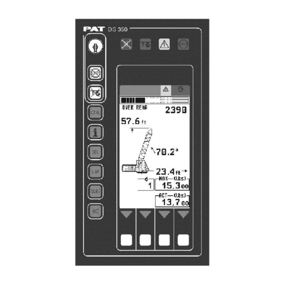
Configuration Setup OPERATION After having set the RCL to the actual crane configuration, the system is ready for operation. The display shows the RCL screen (example for value representation). This example shows a typical operating screen for a crane with a “ main boom” or “ main boom with jib” configuration: utilization bargraph additional text information if required... - Page 23 Operation As needed, further symbols can show on the display: Symbol Anti Two-Block Alarm visible when the anti-two-block limit switch contacts open, indicating that a two-blocking condition is approaching. Symbol Slewing Angle Limitation : continuously visible: Slewing Angle Limitation active ...
-
Page 24: Limit Setting
Operation LIMIT Setting The RCL system has been equipped with programmable limits for the crane's operation range. Easy programming due to interactive, step-by-step user guidance Functions can be used individually or in combinations. Exceeding a programmed limit triggers an audible and visual alarm. ... - Page 25 Operation Radius Limitation This function allows the operator to program an audible and visual alarm for the limitation of a minimum and/or maximum working radius. To set / delete radius limit: Call LIMIT Setting Select the corresponding symbol to call the function "Radius Limitation".
- Page 26 Operation To set / delete minimum radius limit: Screen shows (with To set: To delete: current radius value): Position boom at the desired Push to delete minimum minimum radius. radius limit and exit the function. Push to set current working radius as minimum radius limit.
- Page 27 Operation Tip Height Limitation This function allows the operator to program an audible and visual alarm for the limitation of the tip height. To set / delete tip height limit: Call LIMIT Setting Select the corresponding symbol to select function "Tip Height Limitation".
- Page 28 Operation To set / delete tip height limit: Screen shows (with current tip height To set: To delete: value): Position boom at the desired tip Push to delete tip height height value. limit and exit the function. Push to set current tip height as tip height limit.
- Page 29 Operation Boom Angle Limitation This function allows the operator to program an audible and visual alarm for the limitation of the upper and/or lower boom angle. To set / delete boom angle limits: Call LIMIT Setting Select the corresponding symbol to call the function "Boom Angle Limitation".
- Page 30 Operation To set / delete maximum boom angle limit: Screen shows (with current boom angle To set: To delete: value): Position boom at the desired Push to delete maximum maximum boom angle. boom angle limit and exit the function. Push to set current boom angle as maximum boom angle...
-
Page 31: Slewing Angle Limitation / Virtual Wall Definition
Operation Slewing Angle Limitation / Virtual Wall Definition Programmable function for the limitation of the left and/or right slewing angle or virtual wall definition. To call function: Call LIMIT Setting Select the corresponding symbol to call the slewing limit functions "Slewing Angle Limitation"... - Page 32 Operation Slewing Angle Limitation This function allows the operator to set a left and a right slewing angle limit. Both limits have to be set for the function to be activated, but it does not matter which one is set first. ...
- Page 33 Operation To set / delete left slewing angle limit: Screen shows (with current slewing angle value): To set: To delete: Swing boom to the desired left Push to delete left slewing slewing angle. angle limit and exit the function. Push to set current slewing angle as left slewing angle limit.
- Page 34 Operation To set / delete right slewing angle limit: Screen shows (with current slewing angle value): To set: To delete: Swing boom to the desired right Push to delete right slewing slewing angle. angle limit and exit the function. Push to set current slewing angle as right slewing angle limit.
- Page 35 Operation Virtual Wall Limit The virtual wall limit allows the operator to define a vertical wall that can represent obstacles (i.e. buildings, towers, poles, etc.) in the crane’s working range. The wall is set by defining points with the boom tip within a safe working distance from the obstacle, see setup procedure below.
- Page 36 Operation Virtual Wall Creation Screen The virtual wall creation screen displays the following: the pointed end of the crane symbol indicates the front of the crane the boom is indicated by a line drawn from the center of the crane symbol ...
- Page 37 Operation Having pressed SET, the X is displayed (without blinking) at this point. Move the boom to the second point at a safe distance from the obstacle. This point should be the maximum distance from the first point that can be safely reached by the boom tip.
- Page 38 Operation VIRTUAL WALL EDITING SCREEN Deletes all virtual wall settings and returns to the operating screen. Deletes existing wall and returns to the virtual wall creation screen. Allows the operator to edit the virtual wall by trimming or creating a corner in the wall. Accepts the defined walls and exits to operating screen.
- Page 39 Operation Trimming/Removing the wall to the right of the boom: Edits the wall by trimming/removing the wall to the right of the boom Edits the wall by trimming/removing the wall to the left of the boom. Accepts the defined walls and returns to the editing screen.
- Page 40 Operation Trimming / Removing the wall to the left of the boom Returns to the previous screen Edits the wall by trimming the wall to the right of the boom. Edits the wall by trimming the wall to the left of the boom. Accepts the defined walls and exits Press for trimming/removing the wall to the left of the boom.
-
Page 41: Info Crane Configuration
Operation INFO crane configuration With the system being ready for operation, this function serves to display the system configuration Call function Press “INFO" button. Example: The display shows the crane symbol representing the selected boom configuration (here: main boom 110 ft plus jib 40 ft at a 30... -
Page 42: Display Contrast Control
Operation Display Contrast Control This function allows for the contrast adjustment of the LC display. The last adjustment is stored and will be recalled at every system start. Contrast adjustment Press "CTRL". A pattern is shown which helps setting the display to the optimum contrast. -
Page 43: Pre-Operation Inspection And Calibration Verification
Pre-Operation Inspection and Calibration Verification PRE-OPERATION INSPECTION AND CALIBRATION VERIFICATION Before operating the crane, the following electrical connections must be checked to ensure that the system is properly connected for the crane configuration. If the crane works only with the boom and without boom extension or jib, check bypass plug(s) and the weight on the anti two-block switch(s) is properly installed on the hoist load line(s). - Page 44 Pre-Operation Inspection and Calibration Verification 3. Straighten the cable completely into the slot and release the cable (4). 4. Turn the flag of the retainer for best visibility for the operator (5). Removal and Storage of the Anti Two-Block Retainer Procedure (see Fig. 3 and 4): 1.
- Page 45 Pre-Operation Inspection and Calibration Verification Pre-Operation Inspection and Calibration Verification After the electrical connections have been checked to insure that the system is properly connected for the crane configuration, the following checks shall be made: 1. Check the electrical wiring connecting the various parts of the system for physical damage. 2.
- Page 46 Pre-Operation Inspection and Calibration Verification 6. Check that the display of the main boom angle agrees with the actual boom angles.
- Page 47 If any of the displays reflects a deviation between displayed and actual values, an authorized PAT service representative shall be called for repair of the system or re-verification of crane’s RCL calibration.
-
Page 48: Service And Maintenance
Service and Maintenance SERVICE AND MAINTENANCE Daily maintenance of the Rated Capacity Limiter consists of inspecting: 1. The electrical wiring connecting the various parts of the system. If electrical wiring is damaged, it shall be replaced immediately. 2. If the insulation is worn on the electrical wiring or cable guides are damaged, these parts shall be replaced. -
Page 49: Troubleshooting
TROUBLESHOOTING General In case of a malfunction of the system, the display (1) will indicate a code that identifies the system malfunction. The error codes listed in the Malfunction Table will identify various faults that can occur with the RCL. Following the Malfunction Table are pages, which explain each fault and describe the action, which shall be taken to correct the fault. - Page 50 Troubleshooting Operating Errors Malfunctions in the system, which are caused by, range exceeding or operating errors by the crane operator himself are indicated on the display together with an explanation. These error codes are E01, E02, E03, E04, (E05) and they can normally be eliminated by the crane operator himself.
- Page 51 MANUAL REVISIONS DATE NAME DESCRIPTION HC238 graphic operator’s manual created. 09/15/00...
Need help?
Do you have a question about the DS 350 / 1334 GRAPHIC and is the answer not in the manual?
Questions and answers