Page 1
® INSTALLATION GUIDE 
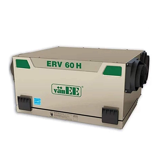
VÄNEE HRV 60H AND ERV 60H Model no.: 41602 Model no.: 41600 (HRV with ports on top) (HRV with ports on sides) VB0076 Model no.: 41606 Model no.: 41604 (ERV with ports on top) (ERV with ports on sides)
ABOUT THIS MANUAL Because of the large amount of models covered by this publication, the illustrations are typical ones. Some details of your unit may be slightly different than the ones shown. Please take note that this manual uses the following symbols to emphasize particular information: WARNING Identifies an instruction which, if not followed, might cause serious personal injuries including possibility of death.
TYPICAL INSTALLATIONS Installations may vary according to the type of unit and the ports configuration (top or sides). Use the following illustrations as guidelines to help you decide on how the unit will be installed. All the units should be hung from the joists. In every case, bathroom fans and a range hood should be used to exhaust stale air.
TYPICAL INSTALLATIONS (CONT’D) 1.4 A ERV U TTIC NSTALLATION FOR NITS All 3 types of installations can be used in the attic (Fully ducted system, Central Draw Point or Simplified). The example shown below is a Simplified installation (connection to a forced air system). CAUTION Due to the potential temperature difference between the attic and the rest of the house, all unit ducts must be insulated.
INSTALLATION (CONT’D) 2.3 U ’ REPARATION CONT The door latches location can be changed from sides to front of the unit, according to the installation needs. VD0176 Latches on sides of the unit Latches in front of the unit To do so, turn the unit upside down. Open the latches an unscrew them from the unit. Install the latches on their new locations. VO0094 VO0090 VO0089...
2. INSTALLATION (CONT’D) 2.5 P LANNING OF THE UCTWORK • Keep it simple. Plan for a minimum of bends and joints. • Keep the length of insulated ducts to a minimum. • Do not ventilate crawl spaces or cold rooms. Do not attempt to recover the exhaust air from a dryer or a range hood. This would cause clogging of the filters and recovery module.
INSTALLATION (CONT’D) 2.6 I ’ NSTALLING THE UCTWORK AND EGISTERS CONT 2.6.3 S 1.3) IMPLIFIED NSTALLATION AS ILLUSTRATED IN ECTION WARNING When performing duct connections, always use approved tools and materials. Respect all corresponding laws and/or safety regulations. Please refer to your local building code. CAUTION When performing duct connections to the furnace supply duct, this duct must be sized to support the additional airflow produced by the HRV/ERV.
INSTALLATION (CONT’D) 2.7 C ONNECTING THE UCTS TO THE Insulated flexible ducts: Use the following procedure for connecting the insulated flexible ducts to the port of the unit ( Exhaust air to outside and Fresh air from outside ports). CAUTION Make sure the balancing dampers are set to their appropriate position before connecting the ducts to the ports.
INSTALLATION (CONT’D) 2.9 I NSTALLING XTERIOR OODS 6” Ø (152 XHAUST HOOD NTAKE HOOD 18’ Choose an appropriate location to install the exterior (457 hoods: 6’ 18” • There must be a minimum distance of 6’ (1.8 m) (1.8 (457 between the hoods to avoid cross-contamination 6’...
CONTROLS (CONT’D) 3.2 E LECTRICAL ONNECTION TO PTIONAL ONTROLS For more convenience, this unit can also be controlled using an optional main wall control. NOTES: 1. The integrated control must be turned OFF to use an optional main control. 2. If an optional auxiliary control is used, if activated, this auxiliary control will override the optional main control. WARNING Always disconnect the unit before making any connections.
CONTROLS (CONT’D) 3.2 E ’ LECTRICAL ONNECTION TO PTIONAL ONTROLS CONT 3.2.4 E LECTRICAL ONNECTION TO PTIONAL UXILIARY ONTROLS 60-MINUTE 20-MINUTED LIGHTED PUSH BUTTON HUMIDITY CONTROL CRANK TIMER (5 MAXIMUM) NOTE: If an optional auxiliary wall control is HUMIDITY CONTROL activated and then, the Humidity NO C NC I OC OL Y R G B Control is being activated, this one...
WIRING DIAGRAM WARNING Risk of electrical shocks. Before performing any maintenance or servicing, always disconnect the unit from its power source. CAUTION Never change both Ref 1 and Ref 2 configurations, only one configuration can be changed at the same time. If Ref 1 and Ref 2 configurations are changed, Medium and Low speed will be reversed.
6. BALANCING THE UNIT To avoid balancing, the difference between stale air ducts total length and fresh air ducts total length must not exceed 50 ft. However, even if the stale air ducts and fresh air ducts lengths are almost equal, your local building codes may require balancing the unit. If the unit does not need to be balanced, shut all the pressure taps (located on the unit door) with the small plastic plugs included in the hardware kit.
7. CONNECTING THE DRAIN (HRV UNITS ONLY) VD0181 From the inner side of the unit door, using the VO0091 provided drain tube, punch out both drain In order to keep the drain pan intact, hand holes (A). tighten the 2 plastic drain fittings to the unit door using the gaskets and nuts as shown.
8. SERVICE PARTS VL0019 41600 HRV 41602 HRV 41604 ERV 41606 ERV ESCRIPTION UMBER PORTS ON SIDES ORTS ON TOP PORTS ON SIDES ORTS ON TOP 5” 16040 VAL PORT FITS DIAMETER DUCTS 16035 OOR LATCH WITH SCREWS VAL PORT WITH INTEGRATED 16041 BALANCING DAMPER &...
9. TROUBLESHOOTING If the integrated control LED of the unit is flashing, this means the unit sensors detected a problem. See the table below to know where on the unit the problem occurs. LED flashes GREEN. • Thermistor error. • Replace the entire port assembly (fresh air from outside port). LED flashes AMBER.
Page 18
9. TROUBLESHOOTING (CONT’D) Problems Possible causes You should try this 9. The supply and/or exhaust • The circuit board may be defective. • Press on the integrated control push button until the unit turn on low motor do not work. speed (the LED will light AMBER).
PIÈCES DE REMPLACEMENT VL0019 41500 VRC 41502 VRC 41504 VRE 41506 VRE ÉF UMÉRO AVEC AVEC AVEC AVEC ESCRIPTION ° DE PIÈCE BOUCHES SUR CÔTÉS BOUCHES SUR DESSUS BOUCHES SUR CÔTÉS BOUCHES SUR DESSUS OUCHE OVALE 16040 CONVIENT AUX CONDUITS DE 16035 OQUETS DE PORTE AVEC VIS OUCHE OVALE ET VOLET DE...
9. DÉPANNAGE S’il survient un problème lors du fonctionnement de l’appareil, le voyant lumineux de l’appareil va clignoter. La couleur du clignotant dépend du type d’erreur détectée. Voyant clignote VERT. • Erreur de thermistor. •Remplacer l’ensemble de bouche-volet motorisé (bouche d’aspiration d’air frais).
Page 21
Problèmes Causes possibles Essayez ceci 9. Le moteur d’aspiration ou • La carte peut être défectueuse. •Appuyer sur le bouton de la commande intégrée pour que l’appareil d’évacuation d’air passe en basse vitesse (le voyant lumineux sera AMBRE). Avec un ne fonctionne pas.
Need help?
Do you have a question about the HRV 60H and is the answer not in the manual?
Questions and answers