Apollo XPA-IN-14102-APO Installation Manual
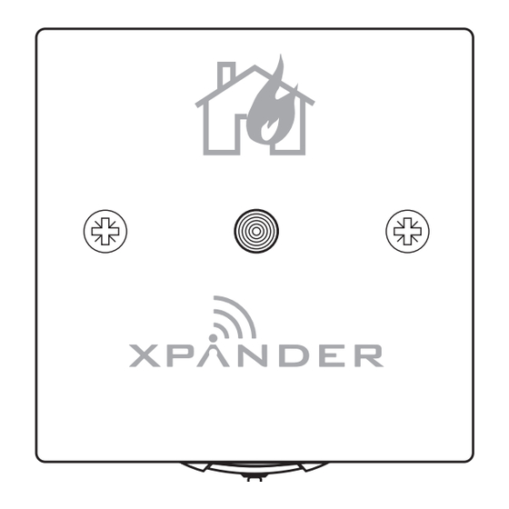
Wireless remote indicator
Hide thumbs
Also See for XPA-IN-14102-APO:
- Commissioning manual (14 pages) ,
- Installation manual (2 pages)
Advertisement
Quick Links
Wireless Remote Indicator
Installation Guide
1 Pre installation
Installation must conform to applicable local installation codes
!
and should only be installed by a fully trained competent person.
•
Ensure that the device is installed as per the site survey.
•
The use of a non-metallic spacer should be considered if mounting the
device on to a metal surface.
•
Do NOT Press the Log On button on a pre-programmed device, as this
will cause communication with the Control Panel to be lost. Should this
happen, delete the device from the system and add it back on.
•
This device contains electronics that may be susceptible to damage
from Electrostatic Discharge (ESD). Take appropriate precautions when
handling electronic boards.
3 Fix mounting plate
•
Remove the mounting plate from the remote indicator. See Step 5 for
more information on unlocking the device.
•
Ensure mounting plate is fitted in the orientation shown.
•
Use both mounting holes.
•
Use suitable fasteners and fixings.
5 Device locking
•
To open the remote indicator,
loosen the fixing screw, then
slide the remote indicator up,
away from the mounting plate.
•
When reassembling, observe the
hinged connection located on
the devices top edge first, prior
to closing the unit. Finally lock
the remote indicator into the
mounting plate by tightening
the fixing screw.
Page 1 of 2
67 mm
57 mm
Fixing screw
Bottom view of
device
Part no
Description
XPA-IN-14102-APO
XPander Remote Indicator
2 Components
3
1
Wireless remote indicator,
4 Power device
•
When fitting / replacing batteries; observe correct polarity, using only
specified batteries.
•
Connect the power jumper across the PIN header.
device
unpowered
(pins unlinked)
device
powered
(both pins linked)
•
Once powered, reassemble the device.
6 Configuration
Refer to the XPander Commissioning Guide (PP2286) for programming details.
Free to download from
www.apollo-fire.co.uk
1
2
2
Mounting plate,
3
Fixing screw
SIZE AA
SIZE AA
SIZE AA
SIZE AA
SIZE AA
39215-219/Issue 3 26/06/2024 AJM
Advertisement

Related Manuals for Apollo XPA-IN-14102-APO


Summary of Contents for Apollo XPA-IN-14102-APO
- Page 1 Part no Description XPA-IN-14102-APO XPander Remote Indicator Wireless Remote Indicator Installation Guide 1 Pre installation 2 Components Installation must conform to applicable local installation codes and should only be installed by a fully trained competent person. • Ensure that the device is installed as per the site survey.
- Page 2 March 2012. Fire detection and fire alarm systems. Part 25: Components using radio links. Operating frequency 868 MHz Apollo declares that this device is in compliance with European Union Output transmitter power Auto adjusting 0 to 14 dBm (0 to 25 mW) Directive 2014/53/EU.
Need help?
Do you have a question about the XPA-IN-14102-APO and is the answer not in the manual?
Questions and answers