Table of Contents
Advertisement
Quick Links
model g0554
gear-head floor
lathe
manual insert
the spindle motor for the Model g0554 has been changed as of August, 2008. the changes to the spindle
motor wiring diagram and parts listing are included in this manual insert.
Keep this insert with your original Model G0554 Owner's Manual for future reference. If you have any
additional questions about this manual insert for the Model G0554, contact our Technical Support at (570)
546-9663 or email techsupport@grizzly.com.
Spindle Motor 3HP, 220V, Single-Phase
to electrical
Control panel
figure 1. Model g0554 spindle motor wiring diagram as of August, 2008.
Copyright © August, 2008 By grizzly industriAl, inC.
Warning: no portion of this manual may be reproduced in any shape
or form Without the Written approval of grizzly industrial, inc.
#ts11022 printed in ChinA
Advertisement
Table of Contents

Subscribe to Our Youtube Channel
Related Manuals for Grizzly G0554


Summary of Contents for Grizzly G0554
- Page 1 Model g0554 has been changed as of August, 2008. the changes to the spindle motor wiring diagram and parts listing are included in this manual insert. Keep this insert with your original Model G0554 Owner's Manual for future reference. If you have any additional questions about this manual insert for the Model G0554, contact our Technical Support at (570) 546-9663 or email techsupport@grizzly.com.
- Page 2 MOTOR 3HP 220V 1PH V2.08.08 941-4V2 P0554941-4V2 S CAPACITOR 800M 250V V2.08.08 941-1v2 P0554941-1V2 MOTOR FAN COVER V2.08.08 941-6V2 P0554941-6V2 R CAPACITOR 60M 250V V2.08.08 941-2V2 P0554941-2V2 MOTOR FAN V2.08.08 941-7V2 P0554941-7V2 WIRING JUNCTION BOX V2.08.08 941-3V2 P0554941-3V2 CAPACITOR COVER V2.08.08 g0554 Manual insert...
- Page 3 MODEL G0554 GEAR-HEAD FLOOR LATHE OWNER'S MANuAL Copyright © MAy, 2006 By grizzly industriAl, inC. WARNiNG: NO pORTiON OF THiS MANuAL MAy bE REpRODucED iN ANy SHApE OR FORM WiTHOuT THE WRiTTEN AppROvAL OF GRizzLy iNDuSTRiAL, iNc. #pC8316 printed in ChinA...
-
Page 5: Table Of Contents
Table of contents iNTRODucTiON ..........................3 Foreword ............................ 3 Contact info ..........................3 Machine data sheet ........................4 identification ..........................6 headstock Controls ........................7 Carriage Controls ........................8 SEcTiON 1: SAFETy ........................9 Additional safety for Metal lathes ................... 11 glossary of terms ........................ - Page 6 SEcTiON 5: AccESSORiES ......................41 SEcTiON 6: MAiNTENANcE......................46 schedule ..........................46 Cleaning ........................... 46 unpainted Cast iron ......................... 46 lubrication ..........................46 Coolant system ........................48 SEcTiON 7: SERvicE ........................49 troubleshooting ........................49 Cross Feed Backlash ....................... 52 gibs ............................
-
Page 7: Introduction
Foreword contact info We are proud to offer the Model g0554 gear- if you have any comments regarding this manual, head Floor lathe. this machine is part of a grow- please write to us at the address below: ing grizzly family of fine metalworking machinery. -
Page 8: Machine Data Sheet
MACHINE DATA SHEET Customer Service #: (570) 546-9663 · To Order Call: (800) 523-4777 · Fax #: (800) 438-5901 MODEL G0554 14" X 40" LATHE Product Dimensions: Weight................................2191 lbs. Length/Width/Height........................80 x 29-1/2 x 45 in. Foot Print (Length/Width)........................73-1/2 x 19 in. - Page 9 The information contained herein is deemed accurate as of 5/26/2006 and represents our most recent product specifications. Model G0554 PAGE 2 OF 3 Due to our ongoing improvement efforts, this information may not accurately describe items previously purchased. g0554 gear-head Floor lathe...
-
Page 10: Identification
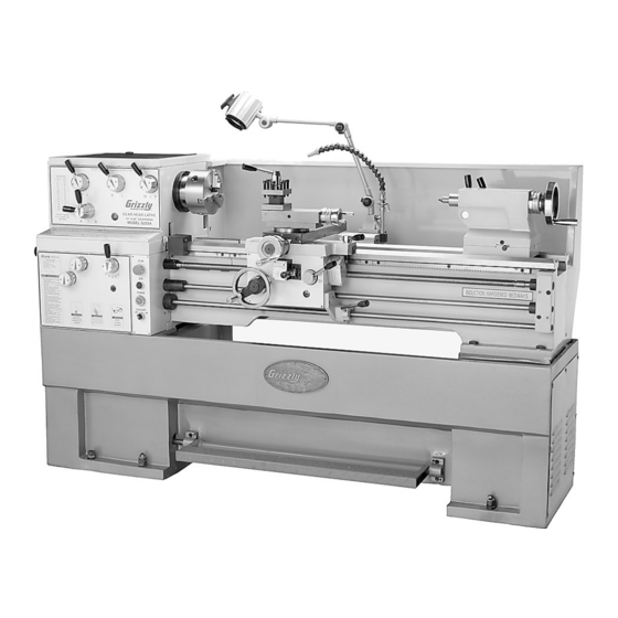
Figure 1. the Model g0554 gear-head Floor lathe. tailstock A. headstock M. tailstock handwheel b. spindle N. Bed Ways c. three-Jaw Chuck O. Bed D. tool post p. gap Bed E. Work light Q. rack Coolant hose R. longitudinal lead screw G. -
Page 11: Headstock Controls
M. Threading chart: shows lever and knob Lead Selection Knob is locked in position. combinations for feed and threading opera- tions. Feed/Lead Selector Lever: used for set- ting up power feed or threading operations in conjunction with threading charts. g0554 gear-head Floor lathe... -
Page 12: Carriage Controls
Figure 3. Model g0554 Carriage controls. A. compound Rest: Adjustable to 120°. G. Thread Dial: used in conjunction with thread cutting. b. compound Handwheel: graduated to 0.001" or 0.02 mm. H. Thread Dial chart: Keys for inputting the desired angle of the saw blade. -
Page 13: Section 1: Safety
SEcTiON 1: SAFETy g0554 gear-head Floor lathe... - Page 14 -10- g0554 gear-head Floor lathe...
-
Page 15: Additional Safety For Metal Lathes
Maintain your lathe in proper working condi- tion. perform routine inspections and main- tenance promptly when needed. put away adjustment tools after use. -11- g0554 gear-head Floor lathe... -
Page 16: Glossary Of Terms
Become familiar with these terms for assembling, adjusting or operating this machine. your safety is Very important to us at grizzly! Arbor: A machine shaft that supports a cutting workpiece in place during cutting operation tool. -
Page 17: Extension Cords
Amperage Draw Electrocution or fire could result if this machine is the Model g0554 motor draws the following not grounded correctly amps under maximum load: or if your electrical con- figuration does not com- Motor draw at 220V....... -
Page 18: Section 3: Setup
Wear safety glasses dur- Unpacking ing the entire setup pro- cess! The Model G0554 was carefully packed when it left our warehouse. If you discover the machine The Model G0554 is is damaged after you have signed for delivery, extremely... -
Page 19: Inventory
M. handwheel handles ........2 Main crate: (Figures 5 & 6) N. open end Wrenches 9/11, 10/12, 12/14, A. Model g0554 gear head lathe ....1 17/14mm ........... 1 each b. 12" Faceplate ..........1 O. hex Wrenches 2.5, 3, 4, 5, 6, & 8mm .. -
Page 20: Cleanup
For opti-... -
Page 21: Moving & Placing Base Unit
Figure 9. lifting the g0554. -17- g0554 gear-head Floor lathe... -
Page 22: Checking Gear Oil
Figure 12. Apron oil sight and fill locations. Figure 14. power light. if necessary, fill the headstock and apron with sAe 20W or iso 68 non-detergent gear oil, or an equivalent lubricant. see Lubrication on page 46 for more information. -18- g0554 gear-head Floor lathe... -
Page 23: Test Run
OFF and the spindle should come to an immediate stop. test the emergency stop Button. the lathe should shut OFF immediately. -19- g0554 gear-head Floor lathe... -
Page 24: Section 4: Operations
SEcTiON 4: OpERATiONS Operation Safety General the Model g0554 will perform many types of operations that are beyond the scope of this man- ual. Many of these operations can be dangerous Damage to your eyes, lungs, and ears could or deadly if performed incorrectly. - Page 25 Note: These cam-locks may be very tight. A breaker bar may be used to add leverage. Figure 17. installing and removing a small chuck. -21- g0554 gear-head Floor lathe...
-
Page 26: Reversing Jaws
(see Figure 18). Figure 19. tightening the cam-locks. Reversing Jaws the three-jaw scroll chucks on the Model g0554 are reversible to hold larger workpieces. Figure 18. Measuring height of cam-lock studs. To reverse the jaws:... - Page 27 —if the workpiece is off center, loosen the jaws and adjust the workpiece. —if the workpiece is seated correctly, tighten the jaws. -23- g0554 gear-head Floor lathe...
-
Page 28: Four-Jaw Direct Mount Independent Chuck
(see Figures 25 & 26). Check frequently to make sure you have not wandered off your center point due to applying too much pressure to a single jaw. -24- g0554 gear-head Floor lathe... -
Page 29: Faceplate
For more objects from a lathe can information refer to centers in this section on cause serious injury or page 30. death to the operator and to bystanders many feet away. -25- g0554 gear-head Floor lathe... -
Page 30: Gap Removal
Gap Removal Tailstock the Model g0554 comes equipped with a gap Quill Feed section below the spindle that can be removed for turning large diameter parts or when using a large diameter faceplate. the gap is installed, then ground at the factory during lathe assembly for precise fit and align- ment. -
Page 31: Drilling With The Tailstock
(see Figure 33). set screw Figure 31. setting up tailstock for drilling. Adjustment screw Figure 33. tailstock off-set adjustments. Figure 32. tapered shank drill fitting into quill taper. -27- g0554 gear-head Floor lathe... -
Page 32: Tailstock Alignment
(see Figure 34). the tailstock on the Model g0554 is aligned at the factory with the headstock. We recommend that you take the time to ensure that the tailstock is aligned to your own desired tolerances. - Page 33 (see Figure 37). 0.010" off of the diameter and check for a taper. repeat this process as necessary until the desired amount of accuracy is achieved. Figure 37. tailstock adjustment option #1. -29- g0554 gear-head Floor lathe...
-
Page 34: Centers
Model g0554 lathe is supplied with two Mt#3 dead centers–one is hss and one is car- install the sleeve and center into the spindle bide tipped. -
Page 35: Steady Rest
Figure 41. steady rest adjustments. tact surface. loosen the knurled screw and open the steady rest so a workpiece can fit inside of the fingers (see Figure 42). -31- g0554 gear-head Floor lathe... -
Page 36: Follow Rest
Be sure to not overtighten, as you may strip threads. -32- g0554 gear-head Floor lathe... -
Page 37: Four-Way Tool Post
Four-Way Tool post Foot brake the four-way tool post is mounted on top of the the Model g0554 lathe comes equipped with compound slide, and allows a maximum of four a foot brake (see Figure 46). the foot brake is tools to be loaded simultaneously. -
Page 38: Manual Feed
Angle adjustment is controlled by cap screws on the base of the compound slide. -34- g0554 gear-head Floor lathe... - Page 39 50) to the appropriate rpM setting. refer to Figure 49 for available rpM and the selector combinations. Note: You may need to rotate the spindle by hand to get the levers to properly engage. SpEEDS LEvERS 1800 1280 Figure 49. rpM chart. -35- g0554 gear-head Floor lathe...
-
Page 40: Power Feed
(see Figure 51). Cross Feed Note: These instructions are valid with a counterclockwise rotation of the spindle. All directions reverse when spindle rotation is reversed. longitudinal Feed Figure 52. power feed lever settings. -36- g0554 gear-head Floor lathe... -
Page 41: Setting Feedrate
Figure 53. Feed rod lock knob. examine the feed/thread chart (Figure 55) to determine the correct lever combination for the desired feedrate. Figure 55. Feed and thread Chart in ipr, tpi and metric pitch. -37- g0554 gear-head Floor lathe... -
Page 42: Thread Settings
Move the selectors to the appropriate letter/ number setting by rotating the handle left or the Model g0554 lathe is capable of cutting inch right. and metric threads. Most inch threads can be cut without changing gears. Metric threads and... -
Page 43: Threading
Note: Setting the gears too tight will cause excessive wear and noise. Setting the gears too loose may cause slippage and possibly break gear teeth. Close the end cover door and reconnect power to the machine. -39- g0554 gear-head Floor lathe... - Page 44 10. if cutting metric threads, you will not use the tion by engaging the half nut lever shown in thread dial. once the half nut is engaged, you Figure 59. must leave it engaged until the threads are complete. -40- g0554 gear-head Floor lathe...
-
Page 45: Section 5: Accessories
ACCessories SEcTiON 5: AccESSORiES this section includes the most common accessories available for this lathe through the grizzly catalog, online at www.grizzly.com, or by calling 1-800-523-4777. G7895—citrus Degreaser G2871—boeshield T-9 12 oz Spray ® this citrus based degreaser is perfect for clean- G2870—boeshield... - Page 46 0.001" and can measure outside surfaces, inside for precision turning. surfaces, and heights/depths. Features stainless steel, shock resistant construction and a dust See the current Grizzly catalog for a full line of proof display. An absolute treat for the perfection- 5-c collets. ist! Figure 66.
- Page 47 64C. tools with carbide inserts, hex wrench, extra hold- down screws and a wooden case. Figure 69. h5687 pre-ground tool Bit set. Figure 71. g5640 5 pc. indexable tool set. -43- g0554 gear-head Floor lathe...
- Page 48 " x 4½", holder is 2¼" x ½", uses centers! these bent tail lathe dogs are made of ⁄ " tool bits. durable cast iron and feature square head bolts. Figure 73. h2996 double ended Boring Bar. Figure 75. h2987-91 lathe dogs. -44- g0554 gear-head Floor lathe...
- Page 49 A super blend of quality and convenience, this live center set offers seven interchangeable tips. high-quality needle bearings prolong tool life and special tool steel body and tips are precision ground. supplied in wooden box. Figure 77. g1070 live Center set. -45- g0554 gear-head Floor lathe...
-
Page 50: Section 6: Maintenance
Change Coolant As needed. or similar lubricant. headstock oil Fill cleaning Cleaning the Model g0554 is relatively easy. Make sure to unplug the lathe before cleaning it. Clean your machine every day or more often headstock oil sight glass as needed. remove chips as they accumulate. - Page 51 • Cross Feed handwheel Apron oil sight glass Apron oil drain Figure 81. Apron lubrication locations. NOTICE Failure to follow lubrication guidelines will lead to rapid deterioration of lathe compo- nents. Figure 82. Ball fitting locations. -47- g0554 gear-head Floor lathe...
-
Page 52: Coolant System
1st and 2nd stage separators. Clean out any remaining debris. Fill the reservoir with approximately three gallons of coolant solution. Closely follow the coolant manufacturer's instructions for mix- ing. -48- g0554 gear-head Floor lathe... -
Page 53: Section 7: Service
4. gear setup is too tight, causing them to bind. 4. readjust the gear setup with a small amount of cut. backlash so the gears move freely and smoothly when the chuck is rotated by hand. -49- g0554 gear-head Floor lathe... - Page 54 Carriage won't 1. gears are not all engaged. 1. Adjust gear positions. feed. 2. gears are broken. 2. replace. 3. loose screw on the feed handle. 3. tighten. -50- g0554 gear-head Floor lathe...
- Page 55 1. Quill lock knob is tightened down. 1. turn knob counterclockwise. not feed out of tailstock. unplug your machine dur- ing all service procedures! ignoring this warning may lead to serious personal injury. -51- g0554 gear-head Floor lathe...
-
Page 56: Cross Feed Backlash
Note: Avoid the temptation to overtighten the socket head cap screw. Overtightening will cause excessive wear to the sliding block and lead screw. -52- g0554 gear-head Floor lathe... - Page 57 Block tighten the front gib screw a quarter turn (see Figure 88. tailstock nut and gib adjustment. Figure 87). Figure 87. Front cross feed and compound rest gib screws. -53- g0554 gear-head Floor lathe...
-
Page 58: Replacing V-Belt
V-belts by loosening the motor mount hex nut (see Figure 89). pulley Belt press ⁄ " Motor Motor pulley Mount Figure 89. V-belt adjustments. -54- g0554 gear-head Floor lathe... -
Page 59: Electrical Components
Electrical components Figure 90. power cord terminal. Figure 92. Brake switch. Figure 93. pump motor. Figure 91. panel switches. -55- g0554 gear-head Floor lathe... -
Page 60: Wiring Diagram
Coolant pump thermal overload Control system spindle Motor step down transformer thermal overload Control system Fuses terminal Bar ground Block Main power switch Figure 94. Model g0554 electrical panel. Figure 95. Model g0554 electrical schematic. -56- g0554 gear-head Floor lathe... -
Page 61: Headstock Assembly
Headstock Assembly -57- g0554 gear-head Floor lathe... -
Page 62: Headstock Assembly
Headstock Assembly -58- g0554 gear-head Floor lathe... -
Page 63: Headstock Assembly
Headstock Assembly -59- g0554 gear-head Floor lathe... -
Page 64: Headstock Parts List
P0554046 SHAFT FORK P6005 BALL BEARING 6005ZZ P0554047 SHIFTING CRANK P0554097 GEAR SHAFT 21T P0554048 STEEL BALL 9 PR18M EXT RETAINING RING 17MM P0554049 COMPRESSION SPRING P0554099 BALL BEARING 61803/P5 P0554050 SHAFT P0554100 GEAR 21T -60- g0554 gear-head Floor lathe... -
Page 65: Headstock Parts List
CAP SCREW M8-1.25 X 16 P0554160 BALANCE SPACE P0554129 COMPRESSION SPRING P0554161 BALANCE BLOCK P0554130 CAMLOCK SET PIN PSS04M SET SCREW M6-1 X 12 P0554131 CAMLOCK PSS14M SET SCREW M8-1.25 X 12 P0554132 SPINDLE PVA67 V-BELT PVA67 -61- g0554 gear-head Floor lathe... -
Page 66: Gearbox Assembly
Gearbox Assembly -62- g0554 gear-head Floor lathe... -
Page 67: Gearbox Assembly
Gearbox Assembly -63- g0554 gear-head Floor lathe... -
Page 68: Gearbox Assembly
Gearbox Assembly -64- g0554 gear-head Floor lathe... -
Page 69: Gearbox Parts List
BALL BEARING 6003ZZ P0554236 SHAFT PR09M EXT RETAINING RING 20MM PRP03M ROLL PIN 5 X 20 P0554277 GEAR 16T/32T P0554238 GEAR 26T P6202 BALL BEARING 6202 P0554239 SHIFT FORK P0554279 GASKET P0554240 SHIFT LEVER P0554280 FLANGE -65- g0554 gear-head Floor lathe... -
Page 70: Gearbox Parts List
INT RETAINING RING 32MM P0554324 COOLANT ON/OFF SWITCH P0554301 BALL BEARING 61804 P0554325 FWD/REV SWITCH P0554302 GEAR 16T P0554326 JOG BUTTON PW23M FLAT WASHER 30MM P0554327 POWER ON LIGHT P0554304 GEAR 21T P0554328 EMERGENCY STOP SWITCH -66- g0554 gear-head Floor lathe... -
Page 71: Apron Assembly
Apron Assembly -67- g0554 gear-head Floor lathe... -
Page 72: Apron Assembly
Apron Assembly -68- g0554 gear-head Floor lathe... -
Page 73: Apron Parts List
O-RING 25.8 X 3.55 P0554435 COLLAR P0554475 APRON LABEL P0554436 BUSHING PS12M PHLP HD SCR M3-.5 X 6 P0554437 SHAFT P0554477 THREAD DIAL LABEL PR06M EXT RETAINING RING 16MM P0554478 INDICATOR LABEL P0554439 GEAR 22T -69- g0554 gear-head Floor lathe... -
Page 74: Carriage Assembly
Assembly -70- g0554 gear-head Floor lathe... -
Page 75: Carriage Parts List
P0554559 OIL CAP P0554528 INDICATOR LABEL P0554560 LOCK STUD P0554529 HOUSING P0554561 FRONT PRESSURE PLATE PSB29M CAP SCREW M6-1 X 40 P0554562 CONNECTED TUBE P8102 THRUST BEARING 8102 P0554563 LAMP BRACKET PW08M FLAT WASHER 16MM -71- g0554 gear-head Floor lathe... -
Page 76: Tool Post Assembly
Tool post Assembly -72- g0554 gear-head Floor lathe... -
Page 77: Tool Post Parts List
PSB11M CAP SCREW M8-1.25 X 16 PK97M KEY 4 X 4 X 14 P0554637 SWIVEL SLIDE PS12M PHLP HD SCR M3-.5 X 6 P0554638 SCALE P0554619 NAME PLATE PS12M PHLP HD SCR M3-.5 X 6 -73- g0554 gear-head Floor lathe... -
Page 78: Tailstock Assembly
Tailstock Assembly -74- g0554 gear-head Floor lathe... -
Page 79: Tailstock Parts List
KEY 3 X 6 X 55 P0554717 WHEEL P0554738 INDICATOR LABEL PSS15M SET SCREW M12-1.75 X 12 PS12M PHLP HD SCR M3-.5 X 6 P0554719 WHEEL SCREW M6 X 15 P0554740 INDICATOR LABEL P0554720 HANDLE LEVER P0554741 INDICATOR LABEL -75- g0554 gear-head Floor lathe... -
Page 80: Bed Assembly
Assembly 855 856 -76- g0554 gear-head Floor lathe... -
Page 81: Bed Parts List
BRACKET P0554827 COLLAR PSS04M SET SCREW M6-1 X 12 P0554828 FEED SHAFT P0554859 PLATE P0554829 COMPRESSION SPRING PSB01M CAP SCREW M6-1 X 16 P0554410 STEEL BALL 6 PRP10M ROLL PIN 5 X 36 P0554831 CLUTCH -77- g0554 gear-head Floor lathe... -
Page 82: Stand Breakdown
Stand breakdown -78- g0554 gear-head Floor lathe... -
Page 83: Stand Parts List
OVERLOAD RELAY 0.35-0.52 P0554924 CONNECTOR BAR P0554947 OVERLOAD RELAY 18-25 PR04M EXT RETAINING RING 6MM P0554948 TRANSFORMER P0554926 DOWEL PIN P0554949 MAIN POWER SWITCH PN09M HEX NUT M12-1.75 P0554950 BRAKE LIMIT SWITCH PW06M FLAT WASHER 12MM -79- g0554 gear-head Floor lathe... -
Page 84: End Gear Assembly
End Gear Assembly -80- g0554 gear-head Floor lathe... -
Page 85: End Gear Parts List
1033 P05541033 REAR PLATE 1016 PW06M FLAT WASHER 12MM 1034 P05541034 PLATE 1017 P05541017 STUD 1035 PSB04M CAP SCREW M6-1 X 10 1018 PK19M KEY 5 X 5 X 14 1036 P05541036 CHANGE GEAR 35T -81- g0554 gear-head Floor lathe... -
Page 86: Steady & Follow Rest Assemblies
Steady & Follow Rest Assemblies -82- g0554 gear-head Floor lathe... -
Page 87: Coolant, Worklight, Boxes, & Thread Dial Assembly
Worklight, boxes, & Thread Dial Assembly 1431 1426 1429 1427 1428 1430 1414 1413 1412 1415 1416 1419 1424 1419-1 1425 1419-3 1420 1421 1419-3 1419-4 1419-5 1418 1418-1 1422-1 1418-2 1423 1418-3 1422 1422-2 -83- g0554 gear-head Floor lathe... -
Page 88: Coolant, Worklight, Boxes, Thread Dial, Steady & Follow Rest Parts List
FLAT WASHER 8MM 1429 P05541429 CAMLOCK STUD SET SCREW 1319 P05541319 KNOB M8-1.25 1430 P05541430 CAST IRON FOOT PAD 1400 P05541400 WORK LIGHT COMPLETE ASSY 1431 P05541431 12" FACE PLATE * NOT SHOWN IN PARTS BREAKDOWN -84- g0554 gear-head Floor lathe... -
Page 89: Safety Label Placement
MuST maintain the original location and readability of the labels on the machine. if any label is removed or becomes unreadable, REpLAcE that label before using the machine again. contact Grizzly at (800) 523-4777 or www.grizzly.com to order new labels. -85-... -
Page 90: Warranty And Returns
WARRANTy AND RETuRNS grizzly industrial, inc. warrants every product it sells for a period of 1 year to the original purchaser from the date of purchase. this warranty does not apply to defects due directly or indirectly to misuse, abuse, negligence, accidents, repairs or alterations or lack of maintenance.
Need help?
Do you have a question about the G0554 and is the answer not in the manual?
Questions and answers