Advertisement
Quick Links
Quick Start Guide
(8200-1953-01_A0)
Tyco Illustra Pro 5MP
Thermal Elevated Skin Temperature Detection Camera
In the box
1 x Camera
4 x PA 4x25mm screws
4 x plastic screw anchors
1 x PW 3x5mm machine screw
4 x 4x10mm screws
1 x L-key hexagonal wrench
1 x Mounting template
1 x Camera adaptor plate
1 x Blackbody device
1 x Quick Start Guide
Installation tools
Screwdriver
L-key hexagonal wrench
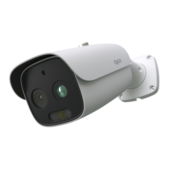
Figure 1: Camera parts
Figure 1
Table 1: Camera part descriptions
Security
Number
1
Camera lens
2
Sun shield cover
3
Sun shield cover adjustment thumb-screw
4
Camera base
5
Pan Adjustment connection
6
Tilt Adjustment connection
Camera body (Buttons and SD card slot are located
on the underside of the camera).
7
Note: You will need to remove the cover to access
them.
Figure 2: Cable connections
Table 2: Cable connection descriptions
Number
1
2
3
4
Figure 3: Camera buttons and SD card slot
Camera part description
Figure 2
Cable connection description
Ethernet Connector and also supports PoE
Audio Input (Max 30V DC / 30mA)
Alarm Output / Input (5V DC @10mA)
Power Connector (12V DC @ 1A)
Figure 3
Figure 3: Camera buttons and SD card slot (continued)
Note: Remove the two screws on the camera cover (1) (Figure 3) to
access the buttons. Securely attach the cover when finished.
Table 3: Camera button descriptions and SD card slot
Number
Camera button description
1
Camera button cover
2
Micro SD Card Slot
3
Reset button (Hold for more than 3 seconds)
Quick reference
Default IP: 192.168.1.168 (DHCP enabled)
Default Username / Password: admin / admin
Power: DC12V / PoE 802.3af
Use Internet Explorer 11 web browser
Use firmware build 'Illustra.S011.01.00.00.9143'
Mounting the camera to a wall or ceiling
1. Place the mounting template on the surface that you want to attach
the camera.
2. On the surface drill four Ø 5mm holes and cut out a >30 Ømm
cable hole as per the markings identified on the mounting template.
3. Securely place the four screw anchors into the four holes.
4. Place the camera cable through the cable hole on the mounting
surface.
5. Hold the camera base (4) (Figure 1) up to the mounting template
and align the four holes on the camera base with the four holes on
the mounting surface.
Mounting the camera to a wall or ceiling (continued)
6. Insert the four PA 4x25mm screws into the four holes on the
camera base and securely attach the camera to the mounting
surface.
7. To power up the camera:
Connect a 12V DC power supply to the power connector on the
camera cable.
OR
Connect the PoE cable to the ethernet / PoE slot on the camera
cable.
Adjusting the sun shield
1. Loosen the thumb-screw (3) (Figure 1) to move the sun shield cover
forward and backward over the camera body (7) (Figure 1).
Note: You must securely lock the thumb screw to ensure that the
sun shield cover holds the modified position.
Adjusting the camera position
1. Use the L-key hexagonal wrench to:
i. Unlock the screw (1) (Figure 4) and pan the camera field of
view up to 360 degrees.
ii. Unlock the screw (2) (Figure 4) to tilt the camera body up to 90
degrees.
iii. Unlock the screw (3) (Figure 4) and rotate the camera body up
to 360 degrees.
Note: You must securely lock each screw to ensure that the camera
holds the modified position.
Advertisement

Related Manuals for Johnson Controls Tyco illustra Pro 5MP


Summary of Contents for Johnson Controls Tyco illustra Pro 5MP
- Page 1 Camera button description (8200-1953-01_A0) Camera base Camera button cover Pan Adjustment connection Tyco Illustra Pro 5MP Micro SD Card Slot Tilt Adjustment connection Reset button (Hold for more than 3 seconds) Camera body (Buttons and SD card slot are located Thermal Elevated Skin Temperature Detection Camera on the underside of the camera).
- Page 2 Figure 5: Camera setup distance recommendations Factors to consider for the environment and installation that can Figure 4: Pan, tilt and rotate screws impact measurement Security Thermal camera is temperature-sensitive. When it is used for temperature measuring, in order to ensure the accuracy, the recommended ambient temperature for operation is 0~35°C and the infrared light should be turned off during the temperature measurement.
- Page 3 © 2020 Johnson Controls. All rights reserved. JOHNSON CONTROLS, TYCO and ILLUSTRA are trademarks and/or registered trademarks. Unauthorized use is strictly prohibited.
Need help?
Do you have a question about the Tyco illustra Pro 5MP and is the answer not in the manual?
Questions and answers