
Related Manuals for Gigabyte GA-X38-DQ6


Summary of Contents for Gigabyte GA-X38-DQ6
- Page 1 GA-X38-DQ6 LGA775 socket motherboard for Intel Core processor family/ ® Intel Pentium processor family/Intel Celeron processor family ® ® ® ® User's Manual Rev. 1002 12ME-X38DQ6-1002R...
-
Page 3: Identifying Your Motherboard Revision
GIGABYTE's prior written permission. Documentation Classifications In order to assist in the use of this product, GIGABYTE provides the following types of documentations: For quick set-up of the product, read the Quick Installation Guide included with the product. -
Page 4: Table Of Contents
Table of Contents Box Contents ......................... 6 Optional Items ......................... 6 GA-X38-DQ6 Motherboard Layout ................7 Block Diagram ........................ 8 Chapter 1 Hardware Installation ..................9 Installation Precautions ..................9 Product Specifications ..................10 Installing the CPU and CPU Cooler .............. 13 1-3-1 Installing the CPU .................... - Page 5 5-1-1 Configuring Intel ICH9R SATA Controllers ............77 ® 5-1-2 Configuring GIGABYTE SATA2 SATA Controller ..........83 5-1-3 Making a SATA RAID/AHCI Driver Diskette ............. 89 5-1-4 Installing the SATA RAID/AHCI Driver and Operating System ...... 90 Configuring Audio Input and Output ..............98 5-2-1 Configuring 2/4/5.1/7.1-Channel Audio ............
-
Page 6: Box Contents
Box Contents GA-X38-DQ6 motherboard Motherboard driver disk User's Manual Quick Installation Guide Intel LGA775 CPU Installation Guide ® One IDE cable and one floppy disk drive cable Four SATA 3Gb/s cables Two SATA brackets I/O Shield Two screws The box contents above are for reference only and the actual items shall depend on product package you obtain. -
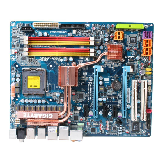
Page 7: Ga-X38-Dq6 Motherboard Layout
GA-X38-DQ6 Motherboard Layout SYS_FAN1 CPU_FAN KB_MS PCIE_12V LGA775 ATX_12V_2X RCA_SPDIF USB_1394_1 USB_1394_2 USB_LAN USB_LAN2 Intel ® RTL8111B AUDIO NB_FAN F_AUDIO PCIE_1 GA-X38-DQ6 RTL8111B PCIE_16_1 PCIE_2 BP_BIOS CODEC PCIE_3 SATAII0 MAIN_BIOS Intel ® ICH9R CLR_CMOS CD_IN PCIE_16_2 SATAII1 GIGABYTE PCI1 SATA2... -
Page 8: Block Diagram
RJ45 PCIe CLK 8111B 8111B Dual BIOS (100 MHz) 6 SATA 3Gb/s PCI Express Bus Intel ® ICH9R 2 SATA 3Gb/s GIGABYTE 12 USB Ports SATA2 ATA-133/100/66/ 33 IDE Channel Floppy PCI Bus LPT Port IT8718 TSB43AB23 COM Port CODEC... -
Page 9: Chapter 1 Hardware Installation
Chapter 1 Hardware Installation Installation Precautions The motherboard contains numerous delicate electronic circuits and components which can become damaged as a result of electrostatic discharge (ESD). Prior to installation, carefully read the user's manual and follow these procedures: Prior to installation, do not remove or break motherboard S/N (Serial Number) sticker or •... -
Page 10: Product Specifications
® ® Intel Celeron processor in the LGA 775 package ® ® (Go to GIGABYTE's website for the latest CPU support list.) L2 cache varies with CPU Front Side Bus 1600/1333/1066/800 MHz FSB Chipset North Bridge: Intel X38 Express Chipset ®... - Page 11 Integrated in the South Bridge Up to 12 USB 2.0/1.1 ports (8 on the back panel, 4 via the USB brackets connected to the internal USB headers) Internal Connectors 1 x 24-pin ATX main power connector 1 x 8-pin ATX 12V power connector 1 x 4-pin PCIe 12V power connector 1 x floppy disk drive connector 1 x IDE connector...
- Page 12 (Note 2) Available functions in Easytune may differ by motherboard model. (Note 3) The adjustable CPU voltage range depends on the CPU being used. (Note 4) Due to chipset limitation, Intel ICH9R RAID driver does not support Windows 2000 operating system. GA-X38-DQ6 Motherboard - 12 -...
-
Page 13: Installing The Cpu And Cpu Cooler
Read the following guidelines before you begin to install the CPU: • Make sure that the motherboard supports the CPU. (Go to GIGABYTE's website for the latest CPU support list.) • Always turn off the computer and unplug the power cord from the power outlet before installing the CPU to prevent hardware damage. - Page 14 CPU notches with the socket alignment keys) and gently insert the CPU into position. Step 5: Once the CPU is properly inserted, replace the load plate and push the CPU socket lever back into its locked position. GA-X38-DQ6 Motherboard - 14 -...
-
Page 15: Installing The Cpu Cooler
1-3-2 Installing the CPU Cooler Follow the steps below to correctly install the CPU cooler on the motherboard. (The following procedure uses Intel boxed cooler as the example cooler.) ® Male Push Pin Direction of the Arrow Sign on the Male The Top Push Pin of Female... -
Page 16: Removing The Crazy Cool Heatsink From The Back Of The Motherboard
Step 5: Do the same for the other screw to complete the removal of the Crazy Cool heatsink. (Note) The components received may vary in appearance from the ones illustrated above. GA-X38-DQ6 Motherboard - 16 -... -
Page 17: Installing The Memory
• Make sure that the motherboard supports the memory. It is recommended that memory of the same capacity, brand, speed, and chips be used. (Go to GIGABYTE's website for the latest memory support list.) • Always turn off the computer and unplug the power cord from the power outlet before installing the memory to prevent hardware damage. -
Page 18: Installing A Memory
Step 2: The clips at both ends of the socket will snap into place when the memory module is securely inserted. GA-X38-DQ6 Motherboard - 18 -... -
Page 19: Installing An Expansion Card
Installing an Expansion Card Read the following guidelines before you begin to install an expansion card: • Make sure the motherboard supports the expansion card. Carefully read the manual that came with your expansion card. • Always turn off the computer and unplug the power cord from the power outlet before installing an expansion card to prevent hardware damage. -
Page 20: Installing The Sata Bracket
SATA device. For SATA device in external enclosure, you only need to connect the SATA signal cable. Before connecting the SATA signal cable, make sure to turn off the power of the external enclosure. GA-X38-DQ6 Motherboard - 20 -... -
Page 21: Back Panel Connectors
Back Panel Connectors PS/2 Keyboard and PS/2 Mouse Port Use the upper port (green) to connect a PS/2 mouse and the lower port (purple) to connect a PS/2 keyboard. Coaxial S/PDIF Out Connector This connector provides digital audio out to an external audio system that supports digital coaxial audio. - Page 22 Only microphones still MUST be con- nected to the default Mic in jack ( ). Refer to the instructions on setting up a 2/4/5.1/ 7.1-channel audio configuration in Chapter 5, "Configuring 2/4/5.1/7.1-Channel Audio." GA-X38-DQ6 Motherboard - 22 -...
-
Page 23: Internal Connectors
Internal Connectors ATX_12V_2X F_AUDIO ATX (Power Connector) CD_IN CPU_FAN SPDIF_IN SYS_FAN1/SYS_FAN2 SPDIF_O PWR_FAN F_USB1/F_USB2 NB_FAN F_1394 PCIE_12V SATAII0/1/2/3/4/5 GSATAIIA/B PWR_LED CLR_CMOS F_PANEL Read the following guidelines before connecting external devices: • First make sure your devices are compliant with the connectors you wish to connect. •... - Page 24 +12V (Only for 2x4 pin 12V) +12V (Only for 2x4 pin 12V) +12V +12V ATX : Pin No. Definition Pin No. Definition 3.3V 3.3V 3.3V -12V PS_ON(soft On/Off) Power Good 5V SB(stand by +5V) +12V +12V 3.3V GA-X38-DQ6 Motherboard - 24 -...
- Page 25 3/4/5) CPU_FAN/SYS_FAN1/SYS_FAN2/PWR_FAN (Fan Headers) The motherboard has a 4-pin CPU fan header (CPU_FAN), a 3-pin (SYS_FAN1) and a 4-pin (SYS_FAN2) system fan headers, and a 3-pin power fan header (PWR_FAN). Each fan header supplies a +12V power voltage and possesses a foolproof insertion design. When connecting a fan cable, be sure to connect it in the correct orientation.
- Page 26 This connector is used to connect a floppy disk drive. The types of floppy disk drives supported are: 360 KB, 720 KB, 1.2 MB, 1.44 MB, and 2.88 MB. Before connecting a floppy disk drive, locate the foolproof groove on the connector. GA-X38-DQ6 Motherboard - 26 -...
- Page 27 9) IDE (IDE Connector) The IDE connector supports up to two IDE devices such as hard drives and optical drives. Before attaching the IDE cable, locate the foolproof groove on the connector. If you wish to connect two IDE devices, remember to set the jumpers and the cabling according to the role of the IDE devices (for example, master or slave).
- Page 28 The SATA connectors conform to SATA 3Gb/s standard and are compatible with SATA 1.5Gb/s standard. Each SATA connector supports a single SATA device. The GIGABYTE SATA2 controller supports RAID 0 and RAID 1. Refer to Chapter 5, "Configuring SATA Hard Drive(s)," for instructions on configuring a RAID array.
-
Page 29: F_Panel Front Panel Header
13) F_PANEL (Front Panel Header) Connect the power switch, reset switch, speaker and system status indicator on the chassis front panel to this header according to the pin assignments below. Note the positive and negative pins before connecting the cables. Message/Power/ Power Speaker... -
Page 30: Cd In Connector
15) CD_IN (CD In Connector) You may connect the audio cable that came with your optical drive to the header. Pin No. Definition CD-L CD-R GA-X38-DQ6 Motherboard - 30 -... -
Page 31: S/Pdif Out Header
16) SPDIF_IN (S/PDIF In Header) This header supports digital S/PDIF in and can connect to an audio device that supports digital audio out via an optional S/PDIF in cable. For purchasing the optional S/PDIF in cable, please contact the local dealer. Pin No. -
Page 32: F_Usb1/F_Usb2 Usb Headers, Yellow
• To connect an IEEE 1394a device, attach one end of the device cable to your computer and then attach the other end of the cable to the IEEE 1394a device. Ensure that the cable is securely connected. GA-X38-DQ6 Motherboard - 32 -... -
Page 33: Tpm (Trusted Platform Module Header)
20) LPT (Parallel Port Header) The LPT header can provide one parallel port via an optional LPT port cable. For purchasing the optional LPT port cable, please contact the local dealer. Pin No. Definition Pin No. Definition STB- AFD- ERR- INIT- ACK- SLIN-... -
Page 34: Battery
• When installing the battery, note the orientation of the positive side (+) and the negative side (-) of the battery (the positive side should face up). • Used batteries must be handled in accordance with local environmental regulations. GA-X38-DQ6 Motherboard - 34 -... -
Page 35: Clearing Cmos Jumper
24) CI (Chassis Intrusion Header) This motherboard provides a chassis detection feature that detects if the chassis cover has been removed. This function requires a chassis with chassis intrusion detection design. Pin No. Definition Signal 25) CLR_CMOS (Clearing CMOS Jumper) Use this jumper to clear the CMOS values (e.g. - Page 36 GA-X38-DQ6 Motherboard - 36 -...
-
Page 37: Chapter 2 Bios Setup
To see more advanced BIOS Setup menu options, you can press <Ctrl> + <F1> in the main menu of the BIOS Setup program. To upgrade the BIOS, use either the GIGABYTE Q-Flash or @BIOS utility. Q-Flash allows the user to quickly and easily upgrade or back up BIOS without entering the •... -
Page 38: Startup Screen
BIOS Setup settings. You can access Boot Menu again to change the first boot device setting as needed. <End>: Q-Flash Press the <End> key to access the Q-Flash utility directly without having to enter BIOS Setup first. GA-X38-DQ6 Motherboard - 38 -... -
Page 39: The Main Menu
The Main Menu Once you enter the BIOS Setup program, the Main Menu (as shown below) appears on the screen. Use arrow keys to move among the items and press <Enter> to accept or enter a sub-menu. (Sample BIOS Version: D19) CMOS Setup Utility-Copyright (C) 1984-2007 Award Software Standard CMOS Features Load Fail-Safe Defaults... - Page 40 (Pressing <F10> can also carry out this task.) Exit Without Saving Abandon all changes and the previous settings remain in effect. Pressing <Y> to the confirmation message will exit BIOS Setup. (Pressing <Esc> can also carry out this task.) GA-X38-DQ6 Motherboard - 40 -...
-
Page 41: Standard Cmos Features
Standard CMOS Features CMOS Setup Utility-Copyright (C) 1984-2007 Award Software Standard CMOS Features Date (mm:dd:yy) Thu, Jul 26 2007 Item Help Time (hh:mm:ss) 18:25:04 Menu Level IDE Channel 0 Master [None] IDE Channel 0 Slave [None] IDE Channel 1 Master [None] IDE Channel 1 Slave [None]... - Page 42 Base Memory Also called conventional memory. Typically, 640 KB will be reserved for the MS-DOS operating system. Extended Memory The amount of extended memory. Total Memory The total amount of memory installed on the system. GA-X38-DQ6 Motherboard - 42 -...
-
Page 43: Advanced Bios Features
Advanced BIOS Features CMOS Setup Utility-Copyright (C) 1984-2007 Award Software Advanced BIOS Features Hard Disk Boot Priority [Press Enter] Item Help First Boot Device [Floppy] Menu Level Second Boot Device [Hard Disk] Third Boot Device [CDROM] Password Check [Setup] HDD S.M.A.R.T. Capability [Disabled] CPU Multi-Threading (Note) - Page 44 With virtualization, one computer system can function as multiple virtual systems. (Default: Enabled) Full Screen LOGO Show Allows you to determine whether to display the GIGABYTE Logo at system startup. Disabled displays normal POST message. (Default: Enabled) Init Display First...
-
Page 45: Integrated Peripherals
Integrated Peripherals CMOS Setup Utility-Copyright (C) 1984-2007 Award Software Integrated Peripherals SATA RAID/AHCI Mode [Disabled] Item Help SATA Port0-3 Native Mode [Disabled] Menu Level USB Controller [Enabled] USB 2.0 Controller [Enabled] USB Keyboard Support [Disabled] USB Mouse Support [Disabled] Legacy USB storage detect [Enabled] Azalia Codec [Auto]... - Page 46 Onboard H/W LAN2 (LAN2 port) Enables or disables the onboard LAN function. (Default: Enabled) If you wish to install a 3rd party add-in network card instead of using the onboard LAN, set this item to Disabled. GA-X38-DQ6 Motherboard - 46 -...
- Page 47 SMART LAN1/LAN2 (LAN Cable Diagnostic Function) CMOS Setup Utility-Copyright (C) 1984-2007 Award Software SMART LAN Start detecting at Port..Item Help Menu Level Pair1-2 Status = Open / Length 0.0m Pair3-6 Status = Open / Length 0.0m Pair4-5 Status = Open / Length 0.0m...
- Page 48 (Default: Enabled) Onboard SATA/IDE Ctrl Mode (GIGABYTE SATA2 Chip) Enables or disables RAID for the SATA controller integrated in the GIGABYTE SATA 2 chip or configures the SATA controller to AHCI mode. Disables RAID for the SATA controller and configures the SATA controller to PATA mode.
-
Page 49: Power Management Setup
Power Management Setup CMOS Setup Utility-Copyright (C) 1984-2007 Award Software Power Management Setup ACPI Suspend Type [S3(STR)] Item Help Soft-Off by PWR-BTTN [Instant-Off] Menu Level PME Event Wake Up [Enabled] Power On by Ring [Enabled] Resume by Alarm [Disabled] x Date (of Month) Alarm Everyday x Time (hh:mm:ss) Alarm 0 : 0 : 0... - Page 50 The system is turned on upon the return of the AC power. Memory The system returns to its last known awake state upon the return of the AC power. (Note) Supported on Windows Vista operating system only. ® ® GA-X38-DQ6 Motherboard - 50 -...
-
Page 51: Pnp/Pci Configurations
PnP/PCI Configurations CMOS Setup Utility-Copyright (C) 1984-2007 Award Software PnP/PCI Configurations PCI1 IRQ Assignment [Auto] Item Help PCI2 IRQ Assignment [Auto] Menu Level : Move Enter: Select +/-/PU/PD: Value F10: Save ESC: Exit F1: General Help F5: Previous Values F6: Fail-Safe Defaults F7: Optimized Defaults PCI1 IRQ Assignment Auto... -
Page 52: Pc Health Status
F, 90 C/194 CPU/SYSTEM/POWER FAN Fail Warning Allows the system to emit warning sound if the CPU/system/power fan is not connected or fails. Check the fan condition or fan connection when this occurs. (Default: Disabled) GA-X38-DQ6 Motherboard - 52 -... - Page 53 CPU Smart FAN Control Enables or disables the CPU fan speed control function. Enabled allows the CPU fan to run at different speed according to the CPU temperature. You can adjust the fan speed with EasyTune based on system requirements. If disabled, CPU fan runs at full speed. (Default: Enabled) Smart FAN Control Mode Specifies how to control CPU fan speed.
-
Page 54: Mb Intelligent Tweaker(M.i.t.)
• When the System Voltage Optimized item blinks in red, it is recommended that you set the System Voltage Control item to Auto to optimize the system voltage settings. (Note) This item appears only if you install a CPU that supports this feature. GA-X38-DQ6 Motherboard - 54 -... - Page 55 Robust Graphics Booster Robust Graphics Booster (R.G.B.) helps to enhance the performance of the graphics chip and memory. Auto allows the BIOS to automatically set the R.G.B. mode based on system configurations. Options are: Auto (default), Fast, Turbo. CPU Clock Ratio (Note) Allows you to alter the clock ratio for the installed CPU.
- Page 56 Options are: Auto (default), 1~31. Refresh to ACT Delay Options are: 0~255 (Default: 0) Read to Precharge Delay Options are: Auto (default), 1~15. Options are: Auto (default), 1~31. tRD Phase Adjustment Options are: Auto (default), 1~31. GA-X38-DQ6 Motherboard - 56 -...
- Page 57 System Voltage Control Determines whether to manually set the system voltages. Auto lets BIOS automatically set the system voltages as required. Manual allows all voltage control items below to be configurable. (Default: Manual) DDR2 OverVoltage Control Allows you to to set memory voltage. Normal Supplies the memory voltage as required.
-
Page 58: Load Fail-Safe Defaults
Press <Enter> on this item and then press the <Y> key to load the optimal BIOS default settings. The BIOS defaults settings helps the system to operate in optimum state. Always load the Optimized defaults after updating the BIOS or after clearing the CMOS values. GA-X38-DQ6 Motherboard - 58 -... -
Page 59: Set Supervisor/User Password
2-12 Set Supervisor/User Password CMOS Setup Utility-Copyright (C) 1984-2007 Award Software Standard CMOS Features Load Fail-Safe Defaults Advanced BIOS Features Load Optimized Defaults Integrated Peripherals Set Supervisor Password Power Management Setup Set User Password PnP/PCI Configurations Save & Exit Setup Enter Password: PC Health Status Exit Without Saving... -
Page 60: Save & Exit Setup
Press <Enter> on this item and press the <Y> key. This exits the BIOS Setup without saving the changes made in BIOS Setup to the CMOS. Press <N> or <Esc> to return to the BIOS Setup Main Menu. GA-X38-DQ6 Motherboard - 60 -... -
Page 61: Chapter 3 Drivers Installation
Chapter 3 Drivers Installation • Before installing the drivers, first install the operating system. (The following instructions use Windows XP as the example operating system.) • After installing the operating system, insert the motherboard driver disk into your optional drive. The driver Autorun screen is automatically displayed which looks like that shown in the screen shot below. -
Page 62: Software Applications
Software Applications This page displays all the tools and applications that GIGABYTE develops and some free software. You may press the Install button following an item to install it. Driver CD Information This page provides information about the drivers, applications and tools in this driver disk. -
Page 63: Hardware Information
Hardware Information This page provides information about the hardware devices on this motherboard. Contact Us Check the contacts information of the GIGABYTE headquarter in Taiwan and the overseas branch offices on the last page of this manual. - 63 -... - Page 64 GA-X38-DQ6 Motherboard - 64 -...
-
Page 65: Chapter 4 Unique Features
Chapter 4 Unique Features Xpress Recovery2 Xpress Recovery2 is an utility that allows you to quickly compress and back up your system data and perform restoration of it. Supporting NTFS, FAT32, and FAT16 file systems, Xpress Recovery2 can back up data on PATA and SATA hard drives and restore it. Before You Begin: •... - Page 66 Recovery2 (10 GB or more is recommended; actual size requirements vary, depending on the amount of data) (Figure 2). Figure 2 Figure 1 3. Select a file system (for example, NTFS) and begin the installation of the operating system (Figure 3). Figure 3 GA-X38-DQ6 Motherboard - 66 -...
- Page 67 4. After the operating system is installed, right-click the My Computer icon on your desktop and select Manage (Figure 4). Go to Computer Management to check disk allocation. Xpress Recovery2 will save the backup file to the unallocated space (black stripe along the top)(Figure 5). Please note that if there is no enough unallocated space, Xpress Recovery2 cannot save the backup file.
- Page 68 Xpress Recovery2 will begin the backup process (Figure 11). Figure 10 Figure 11 3. When finished, go to Disk Management to check disk allocation. Xpress Recovery2 will automatically create a new partition to store the backup image file. Figure 12 GA-X38-DQ6 Motherboard - 68 -...
- Page 69 D. Using the Restore Function in Xpress Recovery2 Select RESTORE to restore the backup to your hard drive in case the system breaks down. The RESTORE option will not be present if no backup is created before (Figure 13, 14). Figure 13 Figure 14 E.
-
Page 70: Bios Update Utilities
4-2-1 Updating the BIOS with the Q-Flash Utility A. Before You Begin: 1. From GIGABYTE's website, download the latest compressed BIOS update file that matches your motherboard model. 2. Extract the file and save the new BIOS file (e.g. X38DQ6.F1) to your floppy disk, USB flash drive, or hard drive. - Page 71 B. Updating the BIOS When updating the BIOS, choose the location where the BIOS file is saved. The follow procedure assumes that you save the BIOS file to a floppy disk. Step 1: 1. Insert the floppy disk containing the BIOS file into the floppy disk drive. In the main menu of Q- Flash, use the up or down arrow key to select Update BIOS from Drive and press <Enter>.
- Page 72 Load Optimized Defaults Press <Y> to load BIOS defaults Step 6: Select Save & Exit Setup and then press <Y> to save settings to CMOS and exit BIOS Setup. The procedure is complete after the system restarts. GA-X38-DQ6 Motherboard - 72 -...
-
Page 73: Updating The Bios With The @Bios Utility
BIOS or a system that is unable to start. 3. Do not use the C.O.M. (Corporate Online Management) function when using @BIOS. 4. GIGABYTE product warranty does not cover any BIOS damage or system failure resulting from an inadequate BIOS flashing. - Page 74 • If the BIOS update file for your motherboard is not present on the @BIOS server site, please manually download the BIOS update file from GIGABYTE's website and follow the instructions in "Update the BIOS without Using the Internet Update Function" below.
-
Page 75: Easytune 5 Pro
Display Area Displays the CPU frequency Function LEDs Shows the supported function(s) Live Update Go to GIGABYTE website to update EasyTune 5 Pro Help Opens EasyTune 5 Pro help file Exit/Minimize Quits or minimizes the EasyTune 5 Pro interface Turbo Boost... -
Page 76: Windows Vista Readyboost
• The USB flash drive must have at least 256 MB of space. • The recommended amount of memory to use for ReadyBoost acceleration is one to three times the amount of RAM installed in your computer. GA-X38-DQ6 Motherboard - 76 -... -
Page 77: Chapter 5 Appendix
"Chapter 1," "Hardware Installation," to identify the SATA controller for the SATA port. (For example, on the GA-X38-DQ6 motherboard, the SATAII0, SATAII1, SATAII2, SATAII3, SATAII4 and SATAII5 ports are supported by ICH9R Southbridge.) Then connect the power connector from your power supply to the hard drive. - Page 78 The BIOS Setup menus described in this section may differ from the exact settings for your motherboard. The actual BIOS Setup menu options you will see shall depend on the motherboard you have and the BIOS version. GA-X38-DQ6 Motherboard - 78 -...
- Page 79 C. Configuring a RAID array in RAID BIOS Enter the RAID BIOS setup utility to configure a RAID array. Skip this step and proceed to the installation of Windows operating system for a non-RAID configuration. Step 1: After the POST memory test begins and before the operating system boot begins, look for a message which says "Press <Ctrl-I>...
- Page 80 Select Disks Strip Size : 128KB Capacity : 223.6 GB Create Volume [ HELP ] The following are typical values: RAID0 - 128KB RAID10 - 64KB RAID5 - 64KB ]-Change [TAB]-Next [ESC]-Previous Menu [ENTER]-Select Figure 5 GA-X38-DQ6 Motherboard - 80 -...
- Page 81 Step 5: Enter the array capacity and press <Enter>. Finally press <Enter> on the Create Volume item to begin creating the RAID array. When prompted to confirm whether to create this volume, press <Y> to confirm or <N> to cancel (Figure 6). Intel(R) Matrix Storage Manager option ROM v7.5.0.1017 ICH9R wRAID5 Copyright(C) 2003-07 Intel Corporation.
- Page 82 [ HELP ] Are you sure you want to delete "Volume0"? (Y/N) : Deleting a volume will reset the disks to non-RAID. WARNING: ALL DISK DATA WILL BE DELETED. ]-Select [ESC]-Previous Menu [DEL]-Delete Volume Figure 8 GA-X38-DQ6 Motherboard - 82 -...
-
Page 83: Configuring Gigabyte Sata2 Sata Controller
"Chapter 1," Hardware Installation," to identify the SATA controller for the SATA port. (For example, on this motherboard, the GSATAIIA and GSATAIIB ports are supported by GIGABYTE SATA2.) Then connect the power connector from your power supply to the hard drive. - Page 84 Figure 2 In the main screen of the GIGABYTE SATA2 RAID BIOS utility (Figure 3), use the up or down arrow key to highlight through choices in the Main Menu block. Highlight the item that you wish to execute and press <Enter>.
- Page 85 In the main screen, press <Enter> on the Create RAID Disk Drive item. Then the Create New RAID screen appears (Figure 4). GIGABYTE Technology Corp. PCIE-to-SATAII/IDE RAID Controller BIOSv1.06.59 [ Create New RAID ] [ Hard Disk Drive List ]...
- Page 86 4. Set Block Size (RAID 0 only): Under the Block item, use the up or down arrow key to select the stripe block size (Figure 6), ranging from 4 KB to 128 KB. Press <Enter>. GIGABYTE Technology Corp. PCIE-to-SATAII/IDE RAID Controller BIOSv1.06.59 [ Create New RAID ]...
- Page 87 When finished, the new RAID array will be displayed in the RAID Disk Drive List block (Figure 8). GIGABYTE Technology Corp. PCIE-to-SATAII/IDE RAID Controller BIOSv1.06.59 [ Main Menu ] [ Hard Disk Drive List ] Create RAID Disk Drive Model Name...
- Page 88 7. Save and Exit Setup: After configuring the RAID array, select the Save And Exit Setup item in the main screen to save your settings before exiting the RAID BIOS utility, then press <Y> (Figure 10). GIGABYTE Technology Corp. PCIE-to-SATAII/IDE RAID Controller BIOSv1.06.59 [ Main Menu ]...
-
Page 89: Making A Sata Raid/Ahci Driver Diskette
For GIGABYTE SATA2 SATA controller, select E) GIGABYTE SATA-RAID Driver 32Bit for • Windows 32-bit operating system or F) GIGABYTE SATA-RAID Driver 64Bit for Windows 64-bit. Your system will then automatically zip and transfer this driver file to the floppy disk. Press <0> to exit when finished. -
Page 90: Installing The Sata Raid/Ahci Driver And Operating System
* If you do not have any device support disks from a mass storage device manufacturer, or do not want to specify additional mass storage devices for use with Windows, press ENTER. S=Specify Additional Device ENTER=Continue F3=Exit Figure 2 GA-X38-DQ6 Motherboard - 90 -... - Page 91 Step 3: For Intel ICH9R SATA controllers: When Setup correctly recognizes the Intel ICH9R SATA RAID/AHCI driver in the floppy disk, a controller menu similar to Figure 3 below will appear. Use the arrow keys to select one of the items displayed and press <Enter>.
- Page 92 Step 3: For GIGABYTE SATA2 SATA controller: When Setup correctly recognizes the GIGABYTE SATA2 SATA RAID/AHCI driver in the floppy disk, a controller menu similar to Figure 5 below will appear. Use the arrow keys to select one of the items displayed and press <Enter>.
- Page 93 Step 4: After the SATA RAID/AHCI driver installation is completed, you can proceed with the Windows XP installation. WindowsXP Professional Setup Welcome to Setup. This port of the Setup program prepares Microsoft(R) Windows (R) XP to run on your computer. To set up Windows XP now, press ENTER.
- Page 94 When a screen similar to that below appears, select Load Driver. (Figure 8). Figure 8 Step 2: Specify the location where the driver is saved, such as your floppy disk (Figure 9). Figure 9 GA-X38-DQ6 Motherboard - 94 -...
- Page 95 Step 3: When a screen as shown in Figure 10 appears, select Intel(R) ICH8R/ICH9R SATA RAID Controller (Note) and press Next. Figure 10 Step 4: After the driver is loaded, select the RAID/AHCI drive(s) where you want to install the operating system and then press Next to continue the OS installation (Figure 11).
- Page 96 GIGABYTE SATA2 controllers: Step 1: Restart your system to boot from the Windows Vista setup disk and perform standard OS installation steps. When a screen similar to that below appears (RAID/AHCI hard drive(s) will not be detected at this stage), select Load Driver. (Figure 12).
- Page 97 Step 3: When a screen as shown in Figure 14 appears, select GIGABYTE GBB36X Controller and press Next. Figure 14 Step 4: After the driver is loaded, select the RAID/AHCI drive(s) where you want to install the operating system and then press Next to continue the OS installation (Figure 15).
-
Page 98: Configuring Audio Input And Output
• 4 channel audio: Front speaker out and Rear speaker out. • 5.1 channel audio: Front speaker out, Rear speaker out, and Center/Subwoofer speaker out. • 7.1 channel audio: Front speaker out, Rear speaker out, Center/Subwoofer speaker out, and Side speaker out. GA-X38-DQ6 Motherboard - 98 -... - Page 99 Step 2: Click the Audio I/O tab. In the speaker list on the left, select 2CH Speaker, 4CH Speaker, 6CH Speaker, or 8CH Speaker according to the type of speaker configuration you wish to set up. Step 3: Everytime you connect an audio device to an audio jack, the Connected device box appears.
-
Page 100: Installing The S/Pdif In Cable (Optional)
A. Installing the S/PDIF In Cable: Step 1: First, attach the connector at the end of the cable to the SPDIF_IN header on your motherboard. Step 2: Secure the metal bracket to the chassis back panel with a screw. GA-X38-DQ6 Motherboard - 100 -... - Page 101 S/PDIF Out: The S/PDIF out jacks can transmit audio signals to an external decoder for decoding to get the best audio quality. B. Conneting a S/PDIF out Cable Connect a S/PDIF coaxial cable or a S/PDIF optical cable (either one) to an external decoder for transmitting the S/PDIF digital audio signals.
-
Page 102: Enabling The Dts (Digital Theater Systems) Function
5.1 channel surround sound playback from two-channel content. (Note) When DTS Interactive is enabled, only digital auio output (S/PDIF) is working, and you will not hear sound from analog speaker or headphone. GA-X38-DQ6 Motherboard - 102 -... -
Page 103: Configuring Microphone Recording
4. Digital PCM Output Setup: In the Audio Control Panel, click the Audio I/O tab. In the upper left list, click Digital PCM Output. Enable this function to allow digital audio sources that are not digitally processed by DTS encoding to be output from the S/PDIF OUT. - Page 104 Do NOT mute the recording sound, or you will not hear any sound when playing back the recording you just made. Select Realtek HD Audio Input in the Mixer device list Recording Control GA-X38-DQ6 Motherboard - 104 -...
-
Page 105: Using The Sound Recorder
Step 6: To raise the recording and playing sound for the microphone, go to Options in Master Volume and select Advanced Controls. Click the Advanced button under a volume control option (e.g. Front Green In, Front Pink In). In the Other Controls field, select the 1 Microphone Boost check box. -
Page 106: Teaming
Teaming Dual LAN with Teaming functionality enabled on this motherboard allows two single connections to act as one single connection for twice the transmission bandwidth, making data transmission more effective and improving the quality of transmission of distant image(s). Fault tolerance on the dual LAN network prevents network downtime by transferring the workload from a failed port to a working port. - Page 107 B. Enabling Teaming Functionality in Windows Vista: Select Realtek Ethernet Teaming Utility and click Install. Step 1: Step 2: Insert the motherboard driver disk and select Soft- Click the Start icon , Point to All Programs, ware Applications. Click Install under Realtek Realtek Teaming and VLAN, Realtek Teaming Ethernet Teaming Utility for installation.
-
Page 108: Troubleshooting
1 long, 2 short: Monitor or graphics card error 1 long, 3 short: Keyboard error 1 long, 9 short: BIOS ROM error Continuous long beeps: Graphics card not inserted properly Continuous short beeps: Power error GA-X38-DQ6 Motherboard - 108 -... -
Page 109: Troubleshooting Procedure
5-4-2 Troubleshooting Procedure If you encounter any troubles during system startup, follow the troubleshooting procedure below to solve the problem. START Turn off the power. Remove all peripherals, connecting cables, and power cord etc. Make sure the motherboard does not short-circuit with the chassis Isolate the short circuit. - Page 110 If the procedure above is unable to solve your problem, contact the place of purchase or local dealer for help. Or go to the Support\Technical Service Zone page to submit your question. Our customer service staff will reply you as soon as possible. GA-X38-DQ6 Motherboard - 110 -...
-
Page 111: Regulatory Statements
"end of life" product. Restriction of Hazardous Substances (RoHS) Directive Statement GIGABYTE products have not intended to add and safe from hazardous substances (Cd, Pb, Hg, Cr+6, PBDE and PBB). The parts and components have been carefully selected to meet RoHS requirement. - Page 112 "end of life" products, and generally improve our quality of life by ensuring that potentially hazardous substances are not released into the environment and are disposed of properly. China Restriction of Hazardous Substances Table The following table is supplied in compliance with China's Restriction of Hazardous Substances (China RoHS) requirements: GA-X38-DQ6 Motherboard - 112 -...
- Page 113 - 113 - Appendix...
- Page 114 GA-X38-DQ6 Motherboard - 114 -...
- Page 115 Contact Us Taiwan (Headquarters) China GIGA-BYTE TECHNOLOGY CO., LTD. NINGBO G.B.T. TECH. TRADING CO., LTD. Address: No.6, Bau Chiang Road, Hsin-Tien, WEB address : http://www.gigabyte.cn Taipei 231, Taiwan Shanghai TEL: +886-2-8912-4888 TEL: +86-21-63410999 FAX: +886-2-8912-4003 FAX: +86-21-63410100 Tech. and Non-Tech. Support (Sales/Marketing) : Beijing http://ggts.gigabyte.com.tw...
- Page 116 Czech Republic WEB address : http://www.gigabyte.co.yu Representative Office Of GIGA-BYTE Technology Co., Ltd. You may go to the GIGABYTE website, select your language in CZECH REPUBLIC in the language list on the top right corner of the website. WEB address : http://www.gigabyte.cz Turkey Representative Office Of GIGA-BYTE Technology Co., Ltd.
Need help?
Do you have a question about the GA-X38-DQ6 and is the answer not in the manual?
Questions and answers