Table of Contents
Advertisement
Quick Links
Installation Instructions
for *R9S80*U Ultra Low
NOx Gas Furnace
CATEGORY I CATÉGORIE I
These furnaces comply with requirements embodied
in the American National Standard/National Standard
of Canada ANSI Z21.47·CSA-2.3 Gas Fired Central
Furnaces.
ATTENTION INSTALLING PERSONNEL
As a professional installer, you have an obligation to know
the product better than the customer. This includes all
safety precautions and related items.
Prior to actual installation, thoroughly familiarize yourself
with this Instruction Manual. Pay special attention to all
safety warnings. Often during installation or repair, it is
possible to place yourself in a position which is more
hazardous than when the unit is in operation.
Remember, it is your responsibility to install the product
safely and to know it well enough to be able to instruct a
customer in its safe use.
Safety is a matter of common sense...a matter of thinking
before acting. Most dealers have a list of specific, good
safety practices...follow them.
The precautions listed in this Installation Manual are
intended as supplemental to existing practices. However,
if there is a direct conflict between existing practices and
the content of this manual, the precautions listed here take
precedence.
RECOGNIZE THIS SYMBOL
AS A SAFETY PRECAUTION
NOTE: Please contact your distributor or our website listed
below for the applicable Specification Sheet referred to in
this manual.
IOG-2039B
01/2024
Installer: Affix all manuals
adjacent to the unit.
19001 Kermier Rd., Waller, TX 77484
www.goodmanmfg.com • www.amana-hac.com
© 2024 Daikin Comfort Technologies Manufacturing, L.P.
is a registered trademark of Maytag Corporation or its related companies and is used under license.
ONLY PERSONNEL THAT HAVE BEEN TRAINED TO INSTALL,
ADJUST, SERVICE, MAINTENANCE OR REPAIR
(HEREINAFTER, "SERVICE") THE EQUIPMENT SPECIFIED IN
THIS MANUAL SHOULD SERVICE THE EQUIPMENT.
THIS EQUIPMENT IS NOT INTENDED FOR USE BY
PERSONS (INCLUDING CHILDREN) WITH REDUCED
PHYSICAL, SENSORY OR MENTAL CAPABILITIES, OR
LACK OF EXPERIENCE AND KNOWLEDGE, UNLESS THEY
HAVE BEEN GIVEN SUPERVISION OR INSTRUCTION
CONCERNING USE OF THE APPLIANCE BY A PERSON
RESPONSIBLE FOR THEIR SAFETY.
CHILDREN SHOULD BE SUPERVISED TO ENSURE THAT
THEY DO NOT PLAY WITH THE EQUIPMENT.
THE MANUFACTURER WILL NOT BE RESPONSIBLE FOR
ANY INJURY OR PROPERTY DAMAGE ARISING FROM
IMPROPER SUPERVISION, SERVICE OR SERVICE
PROCEDURES. IF YOU SERVICE THIS UNIT, YOU ASSUME
RESPONSIBILITY FOR ANY INJURY OR PROPERTY
DAMAGE WHICH MAY RESULT. IN ADDITION, IN
JURISDICTIONS THAT REQUIRE ONE OR MORE LICENSES
TO SERVICE THE EQUIPMENT SPECIFIED IN THIS
MANUAL, ONLY LICENSED PERSONNEL SHOULD
SERVICE THE EQUIPMENT. IMPROPER SUPERVISION,
INSTALLATION, ADJUSTMENT, SERVICING, MAINTENANCE
OR REPAIR OF THE EQUIPMENT SPECIFIED IN THIS
MANUAL, OR ATTEMPTING TO INSTALL, ADJUST, SERVICE
OR REPAIR THE EQUIPMENT SPECIFIED IN THIS MANUAL
WITHOUT PROPER SUPERVISION OR TRAINING MAY
RESULT IN PRODUCT DAMAGE, PROPERTY DAMAGE,
PERSONAL INJURY OR DEATH.
Do not bypass safety devices.
THIS FURNACE MAY BE PAIRED WITH A COOLING UNIT THAT
USES R-32 REFRIGERANT. IF THE COOLING UNIT PAIRED WITH
THIS FURNACE DOES NOT USE R-32, THE R-32 FUNCTION IN
THE FURNACE CONTROL BOARD NEEDS TO BE TURNED OFF.
PLEASE SEE THE ELECTRICAL AND THE R-32 SECTIONS FOR
MORE DETAILS. REFRIGERANT SYSTEMS OTHER THAN 410A
OR R32 MAY REQUIRE AN ADDITIONAL MITIGATION CONTROL
BOARD. REFER TO THE INSTALLATION MANUAL OF THE
INDOOR EVAPORATOR COIL TO DETERMINE INSTALLATION
REQUIREMENTS FOR THAT SUPPLIER'S REFRIGERANT
DETECTION SYSTEM.
All rights reserved.
WARNING
WARNING
WARNING
Advertisement
Table of Contents
Troubleshooting

Related Manuals for Amana R9S80 U Series


Summary of Contents for Amana R9S80 U Series
- Page 1 Specification Sheet referred to in this manual. 19001 Kermier Rd., Waller, TX 77484 www.goodmanmfg.com • www.amana-hac.com © 2024 Daikin Comfort Technologies Manufacturing, L.P. IOG-2039B is a registered trademark of Maytag Corporation or its related companies and is used under license.
-
Page 2: Table Of Contents
TABLE OF CONTENTS SAFETY CONSIDERATIONS IMPORTANT NOTE: This unit is designed to meet the SAFETY CONSIDERATIONS ...........2 NOX requirement of 14Ng/J maximum as required by PRODUCT APPLICATION ..........6 the South Coast Air Quality Management District LOCATION REQUIREMENTS AND CONSIDERATIONS .7 and the San Joaquin Valley Air Pollution Control COMBUSTION AND VENTILATION AIR District, both in the State of California, and is... -
Page 3: Fire Or Explosion Hazard
containing the furnace, the return air shall also be handled by duct(s) sealed to the furnace casing and terminating WARNING outside the space containing the furnace. If the information in these instructions is not followed exactly, a fire or explosion may result causing property A gas-fired furnace for installation in a residential damage, personal injury or loss of life. - Page 4 WARNING AVERTISSEMENT CARBON MONOXIDE POISONING HAZARD RISQUE D’INTOXICATION AU MONOXYDE DE CARBONE Failure to follow the steps outlined below for each ap- Si les étapes décrites ci-dessous ne sont pas suivies pour pliance connected to the venting system being placed into chacun des appareils raccordés au système de ventilation operation could result in carbon monoxide poisoning or au moment de sa mise en marche, cela peut entraîner une...
-
Page 5: Additional Safety Considerations
RISQUE D'EMPOISONNEMENT AU MONOXYDE DE CARBONE Advertencia especial para la instalación de calentadores ó manejadoras de aire en áreas cerradas como estacionamientos ó cuartos de servicio. Cette ventilation est nécessaire pour éviter le danger d'intoxication Las emisiones de monóxido de carbono pueden circular a través au CO pouvant survenir si un appareil produisant du monoxyde del aparato cuando se opera en cualquier modo. -
Page 6: Product Application
To The Installer and 80°F (27°C) is maintained. Before installing this unit, please read this manual • Air filters are installed in the system and replaced thoroughly to familiarize yourself with specific items which daily during construction and upon completion of must be adhered to, including but not limited to: unit construction. -
Page 7: Location Requirements And Considerations
LOCATION REQUIREMENTS AND unit, install the furnace upstream or in parallel with the cooling unit coil. Premature heat exchanger CONSIDERATIONS failure will result if the cooling unit coil is placed ahead of the furnace. For vertical (upflow) applications, the minimum WARNING cooling coil width shall not be less than furnace width minus 1”. -
Page 8: Horizontal Installation
(electrical, flue and drain) may necessitate greater clearances than the minimum clearances listed above. In all cases, accessibility clearance must take precedence over clearances from the enclosure where accessibility clearances are greater. Clearance in accordance with local installation codes, the requirements of the gas supplier and the manufacturer’s installation instructions. -
Page 9: Furnace Suspension
condition; Line contact to framing is permitted when installed in the c. In so far as practical, close all building doors horizontal configuration. Line contact is defined as the and windows and all doors between the space portion of the cabinet that is formed by the intersection of in which the appliance(s) connected to the the top and side. -
Page 10: Category I Venting (Vertical Venting)
WARNING WARNING To avoid property damage, personal injury or death, suffi- To prevent possible personal injury or death doe to asphyx- cient fresh air for proper combustion and ventilation of iation, this furnace must be Category I vented. Do not vent flue gases must be supplied. -
Page 11: Electrical Connections
alteration to comply with electrical codes should not be WARNING required. Wires are color coded for identification purposes. Refer to the wiring diagram for wire routings. If any of the original wire as supplied with the furnace must be Possibility of property damage, personal injury or death damaging condensation can occur inside masonry chim- replaced, it must be replaced with wiring material having neys when a single fan-assisted Category I appliance (80%... - Page 12 box to the right side of the furnace. are located in the blower compartment. The following figure 3. Models that have the junction box located in the shows connections for a “heat only” system and “heat/cool burner compartment will need to move the junction system”.
-
Page 13: Gas Supply And Piping
wiring diagram, located on the blower compartment door, heating operation and the EAC relay will be closed for further details of 120 Volt and 24 Volt wiring. during fan operation. 120VAC must be present on the one terminal from HUM or EAC to take advantage of the A single-stage thermostat with only one heating stage is second terminal. -
Page 14: Natural Gas
or debris has been introduced. Natural Gas Capacity of Pipe In Cubic Feet of Gas Per Hour (CFH) Length of Nominal Black Pipe Size INLET GAS SUPPLY PRESSURE Pipe in Feet 1/2" 3/4" 1" 1 1/4" 1 1/2" Natural Gas Minimum: 4.5"... -
Page 15: Upflow Installations
in contact with masonry, plaster, or insulation, or subjected to repeated wetting by liquids such as Check for leaks using an approved chloride-free soap and water (except rain water), detergents, or sewage. water solution, an electronic combustible gas detector, or The gas piping may enter the left or right side of the other approved testing methods. -
Page 16: Filters - Read This Section Before Installing The Return Air Ductwork
return or two sided return. Supply and return con nections Filters must comply with UL900 or CAN/ULCS111 to the furnace may be made with flexible joints to reduce standards. Damage or repairs due to failure to install filters noise transmission. To prevent the blower from inter fering in the furnace are not covered under the warranty. -
Page 17: Horizontal Installations
COOLING MODE SEQUENCE OF Horizontal Installations Filters must be installed in either the central return register OPERATION or in the return air duct work. 1st Stage Cooling Mode Sequence: NORMAL SEQUENCE OF OPERATION • On a call for low stage cooling, the Y1 or Y1 and G thermostat contacts close signaling the furnace Power Up control board with 24 vac. -
Page 18: Defrost Mode
2nd Stage HP Heating Mode Sequence: begins. NOTE: A Y1 call must be present or a Y2 call will • Following the Gas Heat Mode Fan Off Delay period, be ignored. the indoor fan, EAC, & HUM relays are de-energized. •... - Page 19 through available options corresponding to the main menu Control Board Main Menu item displayed. In the option menu, the default option will Main Menu Option Menu Display Menu Description Additional Info be displayed first. If the default option has been changed SEGT SEGT SEGT...
-
Page 20: Furnace Operation
Furnace operation start blinking or turn OFF. The blinking LED signifies that Purge gas lines of air prior to start-up. Do not purge lines communication with the R-32 sensor is present. The LED into an enclosed burner compartment. Follow NFPA 54, OFF signifies that there is no signal with the sensor. -
Page 21: Gas Supply Pressure Measurement
5. White-Rodgers valves: Push the switch to the OFF position. 6. Wait five minutes then smell for gas. Be sure to check near the floor, as some types of gas are heavier than air. 7. If gas can be smelled following the five minute waiting peri od in Step 6, immediately follow the instructions on Page 3 of this manual. -
Page 22: Gas Manifold Pressure Measurement And Adjustment
NOTE: If measuring gas pressure at the drip leg, a firing. Adjust manifold pressure using the following field-supplied hose barb fitting must be installed Manifold Gas Pressure table. prior to making the hose connection. If using the inlet pressure Tap on the White-Rodgers gas Manifold Gas Pressure valve, then use the 36G/J Valve Pressure Check Kit, Natural Gas... -
Page 23: Circulator Blower Speed Adjustment
rise is usually obtained when the unit is operated at the airflow (CFM) and external static pressure (E.S.P.), for the rated input with the “as shipped” blower speed. If the proper selection of heating and cooling speeds. correct amount of temperature rise is not obtained, it may be necessary to change the blower speed. - Page 24 single stage COOLING) or “AC2” (for Two stage heating speeds will be visible within gAF fan speed COOLING). Press option button and the LED will menu. display the currently selected speed number as Fxx (xx: Blower speed number from 1 to 9). Heat Pump Heating Mode Speed Selection 2.
-
Page 25: Operational Checks
On/Off Fan Delay Selection NOTE: Both readings may be taken simultaneously To change the fan on or off delay for COOLING, HP and read directly on the manometer if so HEATING & GAS HEATING modes, see the following desired. If an air conditioner coil or Electronic Air Cleaner is used in conjunction with the steps: 1. -
Page 26: Troubleshooting
Integrated Control Module then select the option button. The integrated control module is an electronic device which controls all furnace operations. Responding to Clear Fault Memory the thermostat, the module initiates and controls normal To clear all alarm codes, navigate to the last six faults menu, furnace operation, and monitors and addresses all safety L6F, and hold the option button down for 5 seconds. -
Page 27: Cleaning (Qualified Servicer Only)
Filters 3. Do not remove burner or other components. WARNING 4. Clean cabinet and around the inducer blower, motor and burner box. To avoid property damage, personal injury or death, dis- 5. Reconnect wiring. connect electrical power before removing filters. Never 6. -
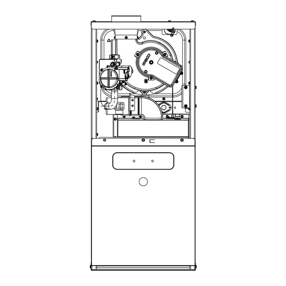
Page 28: Component Id
COMPONENT ID Tubular Heat Exchanger Pressure Sensor Assembly Flue Pipe Connection Gas Line Entrance Gas Valve Inducer Gas Manifold Assembly 8 Burner Assembly Integrated Control Module Blower Door Interlock Switch Circulator Blower 10 Transformer Tubular Heat Exchanger Pressure Switch Gas Line Entrance Gas Valve Inducer Gas Manifold Assembly... -
Page 29: Troubleshooting Charts
TROUBLESHOOTING CHART Symptom Fault Description Corrective Actions Status Normal operation I dL Normal operation None Furnace fails to operate Internal Faults or IRQ Loss in Control Board Replace integrated control board Locate and correct gas interruption Check front cover pressure switch operation and verify proper drainage (hose, wiring, contact operation), correct if Furnace lockout due to an excessive number necessary... - Page 30 TROUBLESHOOTING CHART Symptom Fault Description Corrective Actions Status Furnace fails to operate Polarity of 115 volt AC is reversed Correct polarity, check and correct wiring if necessary Poor unit ground Verify proper ground, correct if necessary Furnace fails to operate Grounding fault Verify neutral wire connection to furnace &...
-
Page 31: Blower Performance Data
BLOWER PERFORMANCE DATA AR9S80-U / GR9S80-U COOLING & CIRCULATION AIFLOW EXTERNAL STATIC PRESSURE (INCHES OF WATER COLUMN) THERMOSTAT MODEL TAP # 0.10 0.20 0.30 0.40 0.50 0.60 0.70 0.80 CALL CFM WATTS CFM WATTS CFM WATTS CFM WATTS *R9S800403AU* Y1/Y2/G F05^ 1058 1015... - Page 32 BLOWER PERFORMANCE DATA...
-
Page 33: Wiring Diagram
WIRING DIAGRAM PRESSURE TRANSDUCER UNUSED 115 VAC/ 1 Ø /60 HZ POWER SUPPLY WITH OVERCURRENT PROTECTION ID BLOWER DEVICE PRESSURE SWITCH WARNING:DISCONNECT POWER BEFORE GAS VALVE SERVICING. WIRING TO UNIT MUST BE PROPERLY POLARIZED DISCONNECT AND GROUNDED. AUTO RESET PRIMARY SURFACE LIMIT CONTROL IGNITER... -
Page 34: Start-Up Checklist
START-UP CHECKLIST... - Page 35 THIS PAGE INTENTIONALLY LEFT BLANK...
-
Page 36: Customer Feedback
Please fill out the feedback form on one of the following links: Goodman Brand Products: (http://www.goodmanmfg.com/about/contact-us). ® Amana Brand Products: (http://www.amana-hac.com/about-us/contact-us). ® You can also scan the QR code on the right for the product brand you purchased to be directed to the feedback page. GOODMAN BRAND ®...
Need help?
Do you have a question about the R9S80 U Series and is the answer not in the manual?
Questions and answers