Advertisement
SERVICE MANUAL
Ver 1.0 2000. 06
• RM-VS10 is the component model block one in RM-VS10TV.
COMPONENT MODEL NAME FOR RM-VS10TV
TRANSMITTER
REMOTE COMMANDER
General
Modulation system
Frequency modulation
Carrier frequency
2.3 MHz (monaural)
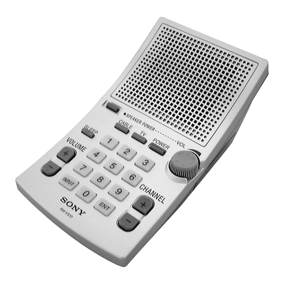
Remote Commander RM-VS10
Power source
Four size AA (R6) batteries (not supplied)/
external DC 4.5 V power sources (AC power
adaptor not supplied)
Maximum speaker output
0.8 W
Battery life (for 5 mW speaker output usage)
Approx. 20 hours (using Sony battery R6)
Approx. 60 hours (using Sony alkaline battery
LR6)
TMR-IF10M
RM-VS10
SPECIFICATIONS
RM-VS10
Remote control operation distance
Approx. 7 m* (23 ft.) (when facing directly
toward the infrared receptor of your TV/analog
cable box)
93 × 86 × 158 mm (3
Dimensions
(w × h × d)
Mass
Approx. 355 g (13 oz.) (including batteries)
* The distance may vary depending on using conditions and
the manufacturer and equipment that is used.
Design and specifications are subject to change without
notice.
Notes on Chip Component Replacement
• Never reuse a disconnected chip component.
• Notice that the minus side of a tantalum capacitor may be
damaged by heat.
SPEAKER REMOTE
COMMANDER SYSTEM
US Model
× 3
× 6
in.)
3/4
1/2
1/4
Advertisement
Table of Contents

Related Manuals for Sony RM-VS10


Summary of Contents for Sony RM-VS10
- Page 1 RM-VS10 SERVICE MANUAL US Model Ver 1.0 2000. 06 • RM-VS10 is the component model block one in RM-VS10TV. COMPONENT MODEL NAME FOR RM-VS10TV TRANSMITTER TMR-IF10M REMOTE COMMANDER RM-VS10 SPECIFICATIONS General Remote control operation distance Modulation system Frequency modulation Approx. 7 m* (23 ft.) (when facing directly Carrier frequency 2.3 MHz (monaural)
-
Page 2: Section 1 Disassembly
SECTION 1 DISASSEMBLY Note : Follow the disassembly procedure in the numerical order given. 1-1. CASE (RX), LOWER 1 lid, battery case 5 foot (A), rubber 6 BTP 2.6x10 4 BTP 2.6x10 3 BTP 2.6x10 7 case (RX), lower case assy (RX), upper 2 knob, volume 1-2. - Page 3 1-3. WIRING METHOD FOR RX BOARD When assembling the RM-VS10, wire as shown in the figure below. FE board hole(boss) install wire so as to be caught between the hole(boss) and C75 RX board – 3 –...
-
Page 4: Section 2 Electrical Adjustments
SECTION 2 ELECTRICAL ADJUSTMENTS Note: 1. The adjustments is performed in the order that they are listed. 2. When adjusting the remote commander, the transmitter is used for adjustment. 3. 0 dB=1.0 V 2-1. Remote commander 2-1-1. Tuning adjustment Method: 1. - Page 5 RM-VS10 SECTION 3 DIAGRAMS 3-1. BLOCK DIAGRAM THIS NOTE IS COMMON FOR PRINTED WIRING BOARDS AND SCHEMATIC DIAGRAMS. (In addition to this, the necessary note is printed in each block.) FE BOARD RX BOARD for Schematic Diagram: • All capacitors are in µF unless otherwise noted. pF: µµF...
- Page 6 RM-VS10 3-2. PRINTED WIRING BOARDS • Refer to page 6 for Note. RX BOARD (CARBON PATTERN SIDE) SPEAKER SLEEP POWER VOLUME INPUT CABLE POWER 1-678-157- (11) CHANNEL – 7 – – 8 –...
- Page 7 RM-VS10 • Refer to page 6 for Note. PD BOARD DC IN 4.5V EARPHONE 1-678-160- (11) RX BOARD (CONDUCTOR SIDE) TP19 IC52 IC55 RM BOARD TP21 TP20 SPEAKER POWER INFRARED EMITTER IC51 1-678-159- (11) SPEAKER DRY BATTERY UM-3x4 FE BOARD...
- Page 8 RM-VS10 3-3. SCHEMATIC DIAGRAM • Refer to page 5 for IC Block Diagram. Refer to page 6 for Note. • Waveforms (When pressing the buttons on the commander) 0.1V/div 0.1µsec/div 0.1V/div 10µsec/div 2.0Vp-p 2.0Vp-p 4MHz IC52 (OSC2) IC53 (FILTER-OUT) – 11 –...
-
Page 9: Section 4 Exploded Views
SECTION 4 EXPLODED VIEWS NOTE: • The mechanical parts with no reference • -XX and -X mean standardized parts, so • Accessories and packing materials and number in the exploded views are not supplied. they may have some difference from the hardware (# mark) list are given in •... -
Page 10: Section 5 Electrical Parts List
SECTION 5 ELECTRICAL PARTS LIST NOTE: • Due to standardization, replacements in • Items marked “*” are not stocked since When indicating parts by reference the parts list may be different from the they are seldom required for routine service. number, please include the board. - Page 11 Ref. No. Part No. Description Remark Ref. No. Part No. Description Remark < IC > < COIL > IC51 8-759-583-17 IC BU2305F-E2 1-406-915-11 COIL (DET) IC52 8-759-586-60 IC MN9807SP-E1 IC53 8-759-375-39 IC MC3361CD < VARIABLE RESISTOR > IC54 8-759-701-54 IC NJM2073D IC55 8-759-431-95 IC S-81230SGUP-DQB-T1 VR51...
- Page 12 RM-VS10 Sony Corporation 2000F0412-1 9-927-963-11 Audio Entertainment Group Printed in Japan ©2000. 6 – 16 – Published by PE General Engineering Dept.
Need help?
Do you have a question about the RM-VS10 and is the answer not in the manual?
Questions and answers