Advertisement
Quick Links
SolarEdge
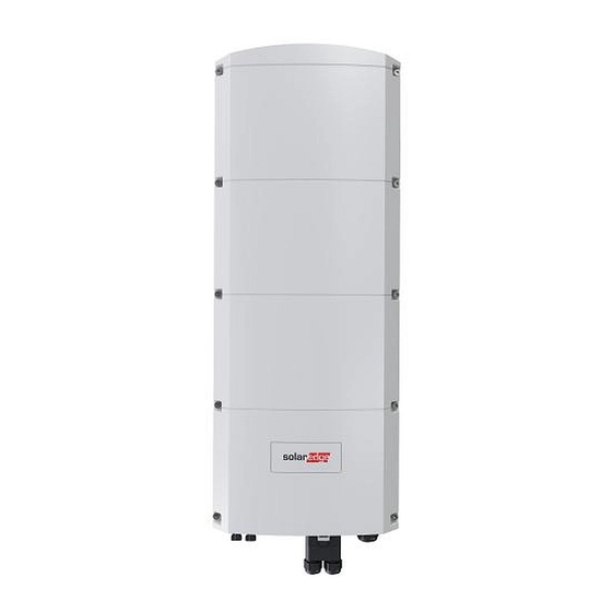
Home Hub Inverter -
Three Phase
Quick Installation Guide
V1.2
What's in the Package
Inverter
Wall mount
DC connection
bracket
box
WARNING!
This symbol denotes a hazard. The symbol calls attention to a procedure that could result in injury or loss
of life if not correctly performed or adhered to. Do not proceed beyond a warning note until the
conditions are fully understood and met.
CAUTION! Denotes a hazard. The symbol calls attention to a procedure that could result in damage or
destruction of the product if not correctly performed or adhered to. Do not proceed beyond a caution sign until
the indicated conditions are fully understood and met.
Backup System Installation
IMPORTANT NOTE! When installing or upgrading your backup
system:
1. First, install the Inverter.
2. Next, install the Battery.
3. Finally, if applicable, install the Backup Interface (BUI).
Mounting
A
CAUTION! DO NOT rest
the inverter vertically on
the connectors
4
3
4 N*m
5
CAUTION! Do not
block airflow
SolarEdge Home
Antenna
Ferrite
Cable lugs
Network Antenna
bracket
Bead
10 cm
10 cm
Optional antenna location
37 KG
2
Optional
1
6
4
1
7
10
5
6
9
8
3
2
solaredge.com
SolarEdge Technologies GmbH, Werner-Eckert-Str. 6, 81829 Munich, Germany
Subject to change without notice.
© SolarEdge Technologies, Ltd.
All rights reserved. February 2024.
Up-to-Date Quick
Unpacking and
Installation Guide
Mounting Video
SolarEdge declares that the Home Hub Inverter – Three Phase
family of products is compliant with EU RED Directive 2014/53/EU
Tools and Materials
Compact guide,
warranty card, and
specification sheet
Phillips/Flat-Blade
Wiring
B
WARNING!
POWER AND WAIT FOR 5 MINUTES BEFORE INSTALLATION OR
SERVICE
WARNING!
the Safety and Handling instructions provided with this product.
L1 L2 L3 N
2
WARNING! Connect a
ground cable according
to local regulation.
Wiring Video
Datasheet
Drill
Pencil
Level
Open-end
Torque wrench
Hammer
torque
with 10 mm socket hex
wrench
and 5 mm Allen bit
Small Flat-Blade
Mounting screws and
screwdriver set
Screwdriver
wall plugs - max M10
HAZARD OF ELECTRIC SHOCK. DISCONNECT
Before installing or operating the Inverter, read
WARNING! connect the grounding wire first
Ferrule
AC
(For stranded wires
4
8 mm
1.5 N*m
1
3
OFF
5
CAUTION! DO NOT
DC
use a circuit breaker
with a rated current
of more than 20A
PV String(s)
Full Installation
Guide
Crimping tool
Wire Cutter
min 2
Manual Shutdown
Switch
)
2.5-16 mm
2
15-21 mm
Advertisement

Summary of Contents for SolarEdge SE10K-RWB
- Page 1 Mounting Video Wiring Video Datasheet Guide V1.2 What’s in the Package SolarEdge declares that the Home Hub Inverter – Three Phase family of products is compliant with EU RED Directive 2014/53/EU Tools and Materials Inverter Wall mount DC connection SolarEdge Home...
- Page 2 IMPORTANT! The connection to units and accessories shown here is for reference only. For detailed information, refer to the specific product guide. SolarEdge Home Network Connection Battery Connection Communication Cable 1.1 N*m Inline Meter 2.2 N*m Smart Energy Hot Water...


Need help?
Do you have a question about the SE10K-RWB and is the answer not in the manual?
Questions and answers