Table of Contents
Advertisement
Quick Links
DESIGN, INSTALLATION, OPERATION, AND
MAINTENANCE MANUAL
FOR
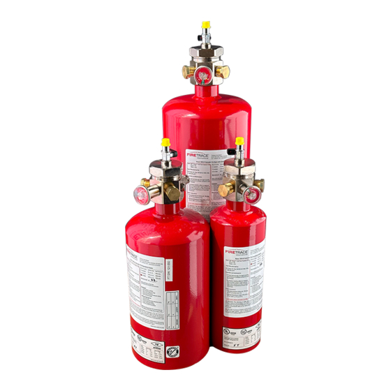
CLEAN AGENT SELF CONTAINED AUTOMATIC FIRE EXTINGUISHER UNITS
DESIGNED FOR USE WITH:
FK-5-1-12 FIRE PROTECTION AGENT
940205 CYLINDER ASSEMBLY, DOT, ILP, M10X1 GAUGE, FK-5-1-12, 2.5LB
940555 CYLINDER ASSEMBLY, DOT, ILP, M10X1 GAUGE, FK-5-1-12, 5LB
941055 CYLINDER ASSEMBLY, DOT, ILP, M10X1 GAUGE, FK-5-1-12, 10LB
942055 CYLINDER ASSEMBLY, DOT, ILP, M10X1 GAUGE, FK-5-1-12, 20LB
Document: 800027-A (DIOM, ILP, DOT, FK-5-1-12, 195 PSI)
Firetrace International, LLC
8435 N. 90
St, Suite 2
TH
Scottsdale, AZ 85258 USA
Telephone: 480-607-1218
Fax: 480-315-1316
www.firetrace.com
Advertisement
Table of Contents

Related Manuals for FIRETRACE FK-5-1-12


Summary of Contents for FIRETRACE FK-5-1-12
- Page 1 CLEAN AGENT SELF CONTAINED AUTOMATIC FIRE EXTINGUISHER UNITS DESIGNED FOR USE WITH: FK-5-1-12 FIRE PROTECTION AGENT 940205 CYLINDER ASSEMBLY, DOT, ILP, M10X1 GAUGE, FK-5-1-12, 2.5LB 940555 CYLINDER ASSEMBLY, DOT, ILP, M10X1 GAUGE, FK-5-1-12, 5LB 941055 CYLINDER ASSEMBLY, DOT, ILP, M10X1 GAUGE, FK-5-1-12, 10LB...
- Page 2 DESCRIPTION OF CHANGE Appvd DATE Initial Release DCR23-019 06/05/2023 DESIGN, INSTALLATION, OPERATION, AND MAINTENANCE MANUAL CLEAN AGENT SELF CONTAINED AUTOMATIC FIRE EXTINGUISHER UNITS 800027-A 06/05/2023...
-
Page 3: Table Of Contents
........................... 23 AXIMUM ROTECTED OLUME IMITATIONS 4.6.1 Class A Fires (All FK-5-1-12 agents) ..........................23 4.6.2 Class B Fires (All FK-5-1-12 agents) ..........................23 4.6.3 Class C Fires (3M™ Novec™ 1230, Noah NY5112 & Dukare 1230) ................... 24 4.6.4 Class C Fires (Waysmos FK-5-1-12)........................... 24... - Page 4 IRES AYSMOS 5112™)................................54 LASS IRES HEMORI APPENDIX C – COMMISSIONING DOCUMENT CHECKLIST ........................ 56 APPENDIX D - SAFETY DATA SHEET 3M™ NOVEC™ 1230 FIRE PROTECTION FLUID ................57 APPENDIX E - SAFETY DATA SHEET WAYSMOS FK-5-1-12......................... 66 800027-A 06/05/2023...
- Page 5 Table 23 – Class C Minimum Design Concentrations (3M™ Novec™ 1230, Noah NY5112 & Dukare 1230) ............... 22 Table 24 – Class C Minimum Design Concentrations (Waysmos FK-5-1-12) ........................ 22 Table 25 – Class C Minimum Design Concentrations (Chemori 5112™) ........................22 Table 26 –...
- Page 6 Table 29 – Class C Fire Enclosure Volume Limitations (Waysmos FK-5-1-12) ......................24 Table 30 – Class C Fire Enclosure Volume Limitations (Chemori 5112™) ........................24 Table 31 – Atmospheric Correction Factor ..................................25 Table 32 – Nozzle Area Coverage Limitations ................................26 Table 33 –...
-
Page 7: Foreword
Firetrace assumes no responsibility for the design or function of any systems other than those addressed in this manual. The technical data contained herein is limited strictly for informational purposes only. -
Page 8: Safety Precautions
3. Wear safety glasses when working with pressurized cylinders and charging equipment. It is recommended to wear leather gloves to avoid any cryogenic burns if FK-5-1-12 is accidentally discharged on or near the skin. 4. Make sure that the ball valve (attached to the top of the cylinder valve) is closed (lever is in “OFF” position), the detection tubing has been removed from the cylinder valve and the safety caps installed before removing the cylinder from the installation and before performing any charging, leak tests or salvage operations. -
Page 9: Introduction
C fires. FK-5-1-12 is included in NFPA 2001 and has been evaluated and approved for use in occupied areas as a Total Flooding agent, when used as specified under the U.S. Environmental Protection Agency (EPA) SNAP Program rules. Refer to the SNAP Program rules for more information. -
Page 10: Properties Of Fk-5-1-12
UPS units For hazards beyond the scope described above, it is recommended that the designer consult with Firetrace and the Local Authority Having Jurisdiction (AHJ) as to the suitability on the use of these agents for particular hazards, for personnel exposure effects from the design concentration, and for installation requirements. -
Page 11: Component Descriptions
3.2 FK-5-1-12 Cylinders (100300, 100600, 101200, 120020) FK-5-1-12 is stored in steel cylinders pressurized with nitrogen to 195 psig at 70°F (13.4 bar at 21°C). Table 3-1 describes the 2.5, 5, 10 and 20 Lb system assemblies. Each cylinder is equipped with a straight siphon tube and can only be mounted in a vertical (upright) position (±30°). -
Page 12: Cylinder Mounting Bracket (100003, 100006, 111206, 111020)
This precaution is intended to safely support the weight of the cylinder and the reaction force of the FK-5-1-12 discharge. -
Page 13: Cylinder Valves (300112 & 302118)
Each cylinder is equipped with a nickel-plated brass valve. The cylinder valves are backpressure type design. A piston in the valve bore is equipped with a seat seal that keeps the FK-5-1-12 clean agent under pressure within the cylinder. A small hole in the piston allows cylinder pressure to equalize on both sides of the piston. -
Page 14: Firetrace Detection Tubing (200005)
Failure to follow these instructions could result in property damage, personal injury, or death. NOTE: All Firetrace FK-5-1-12 ILP Units utilize a straight siphon tube. All Firetrace FK-5-1-12 ILP Units are to be installed only in a vertical (valve on top) position. -
Page 15: Table 8 - Firetrace Detection Tubing Properties
1300 psi [88 bar] Volume Resistivity 1014 (per DIN 53481) Electrical Properties Dielectric Strength 40k V/mm (per DIN 53481) Table 9 – Firetrace Detection Tube Part Numbers Firetrace Detection Description Tubing Part Number 200005 Firetrace Detection Tubing, 4/6 mm, 1 ft... -
Page 16: Firetrace Detection Tubing Fittings
NP – PARTS NOT PICTURED 3.5 Pressure Gauge (400195) The Firetrace FK-5-1-12 pressure gauge, is used as part of the cylinder valve pressure gauge, manual release pressure gauge or End of Line mounted pressure gauge. This pressure gauge is supplied with an O-ring installed, and has a M10x1 thread to allow for installation where a Schrader core is present. This enables the pressure gauge to be field serviceable in all the above applications (cylinder valve, manual release and End of Line mounted locations). -
Page 17: Manual Release (600055)
Figure 4 – FK-5-1-12 Pressure Gauge 3.6 Manual Release (600055) The manual release is used as an optional part of the system detection line network. The manual release is used to manually release the nitrogen pressure in the tubing, causing the system to actuate. The actuation results in a complete discharge of the unit assembly. -
Page 18: Manual Release Rebuild Kit (600076)
All piping must be installed in accordance with good commercial practices and applicable national standards. 3.7.1.1 Pipe Requirements Recommended piping to be used for Firetrace ILP Units is copper. Piping shall be in accordance with the requirements of NFPA 2001 or the local authority having jurisdiction. -
Page 19: Figure 6 - Flexible Hoses
3.7.2.2 Flexible Hose Fittings The flexible hose fittings are constructed of zinc plated steel. The flexible hose fittings allow for easy installation between the Firetrace FK-5-1-12 ILP Units, the flexible hoses, and the system nozzles. The flexible hose fittings have a minimum burst rating of 3000 psig [206.8 bar]. Refer to Table 11 –... -
Page 20: Nozzles (500015 500120)
Nozzles (500015 500120) Discharge nozzles are made of nickel-plated brass with female pipe threads. Nozzles are available in two sizes for use with Firetrace ILP FK-5-1-12 Units. The small nozzles contain a G1/4 thread. The medium nozzles contain a 1/2 in NPT thread. The 940205 unit assembly uses the small nozzle, see Figure 8 –... -
Page 21: Pressure Switch (400001)
NOTE: All detection devices and auxiliary alarm and control devices must be electrically compatible with each other. They must be approved by the authority having jurisdiction. NOTE: Firetrace recommends that all units be equipped with a pressure switch and connected into a notification or shutdown device, in the event of a discharge. -
Page 22: Figure 10 -Pressure Switch Wiring Schematic
Table 13 – Valve Mounted Pressure Switch Part Number Pressure Switch Part Description Number 400001 Valve Mounted Pressure Switch Figure 10 –Pressure Switch Wiring Schematic Table 14 – Pressure Switch Properties Electrical Rating Temperature Range 28 VDC – 15 A -20 °F to 150 °F NO (1 and 3): NC (1 and 2):... -
Page 23: End Of Line Pressure Switch (400004)
NOTE: All detection devices and auxiliary alarm and control devices must be electrically compatible with each other. They must be approved by the authority having jurisdiction. NOTE: Firetrace recommends that all units be equipped with a pressure switch and connected into a notification or shutdown device, in the event of a discharge. -
Page 24: Pressure Switch Assembly (400441)
NOTE: All detection devices and auxiliary alarm and control devices must be electrically compatible with each other. They must be approved by the authority having jurisdiction. NOTE: Firetrace recommends that all units be equipped with a pressure switch and connected into a notification or shutdown device, in the event of a discharge. -
Page 25: Alarm Module - Battery Operated (600096)
The electric solenoid assembly is used to release pressure from the detection tubing, resulting in actuation of the Firetrace FK-5-1-12 ILP Unit. Refer to Figure 14 – Electric Solenoid Assembly, Table 17 – Electric Solenoid Assembly Part Number, Figure 15 – Electric Solenoid Assembly Wiring Schematic, and Table 18 –... -
Page 26: Figure 14 - Electric Solenoid Assembly
Figure 14 – Electric Solenoid Assembly Table 17 – Electric Solenoid Assembly Part Number Electric Solenoid Description Assembly Part Number 400312 12 VDC Electric Solenoid Assembly 400324 24 VDC Electric Solenoid Assembly 600088 Solenoid Valve Wiring Harness 200107 Solenoid to Ball Valve Adapter Figure 15 –... -
Page 27: System Design And Limitations
Chemicals capable of undergoing autothermal decomposition. 4.2 Specifications 4.2.1 Storage and Operating Temperature Range The Firetrace FK-5-1-12 Units and equipment are designed to be stored and operated at the ambient temperature range of 0°F to +130°F (-17.8°C to +54.4°C). 4.2.2 System Operating Pressure The normal operating pressure for the unit is 195 psig at 70°F (13.4 bar at 21°C). -
Page 28: Design Procedure
Table 19 - Cylinder Pressure-Temperature Relationship 4.3 Design Procedure The following procedures should be used to design a Firetrace FK-5-1-12 Self-Contained Automatic Indirect Fire Suppression Unit. In addition, the applicable requirements specified in Chapter 5 of NFPA 2001 should be followed. -
Page 29: Required Amounts Of Agent
Minimum Design Concentrations The minimum design concentrations to be used with Firetrace FK-5-1-12 units include a minimum safety factor (SF), as specified in NFPA 2001. Consult the Firetrace website, or contact Firetrace if the hazard you desire to protect is not listed. -
Page 30: Table 21 - Class A Minimum Design Concentrations
The maximum volume limitations and minimum temperature specifications MUST be followed in order to maintain the correct safety factor. It is recommended that the designer consult with Firetrace, NFPA 2001, and the local authority having jurisdiction, as to the suitability on the use of FK-5- 1-12 for a particular hazard, for personnel exposure effects from the design concentrations, and for installation requirements. -
Page 31: Actual Concentration
NFPA 2001. 4.6 Maximum Protected Volume Limitations The maximum volume that can be protected by the Firetrace FK-5-1-12 units is dependent on the design concentration and the minimum ambient design temperature specified for a given hazard. -
Page 32: Class C Fires (3M™ Novec™ 1230, Noah Ny5112 & Dukare 1230)
266.2 7.54 532.3 15.07 4.6.4 Class C Fires (Waysmos FK-5-1-12) Table 29 – Class C Fire Enclosure Volume Limitations (Waysmos FK-5-1-12) Maximum Enclosure Volume (Class C Hazard @4.890vol%) Waysmos FK-5-1-12 Only Design Temperature 940205 (2.5 lb) 940555 (5 lb) 941055 (10 lb) 942055 (20 lb) °F... -
Page 33: Altitude Correction Factor (Acf)
4.6.6.1 MCF Example If the calculated agent quantity was 18 lbs (8.17 kg) of FK-5-1-12 and the altitude was 2,000 ft (0.61 km) above sea level – the resulting ACF should be applied from the table as “0.93”, which is 93% of the calculated mass at sea level, using the MCF column: 18 lbs (8.17 kg) x 0.93 = 16.74 lbs (7.60 kg) -
Page 34: Nozzle And Discharge Pipe Requirements
Nozzle Area Coverage Table 32 – Nozzle Area Coverage Limitations below shows the nozzle area coverage limitations for Firetrace Pre-Engineered FK-5-1-12 ILP Automatic Suppression Units. The maximum enclosure height for nozzle installation is 10 ft [3.05 m]. The minimum enclosure height for nozzle installation is 1.6 ft [0.3 m]. -
Page 35: Discharge Piping And Fitting Specifications
Discharge Piping and Fitting Specifications All Firetrace ILP Units shall use copper tubing or equivalent, or the Firetrace discharge hoses for the FK-5-1-12 distribution system. The following tubing and fittings shall be used. Refer to NFPA 2001, 2015 Edition - Section 4.2 for alternate discharge network options. -
Page 36: Discharge Pipe Bends
Table 36 – Discharge Piping Limitations Maximum Length of Discharge Nozzles per Total Nozzles Discharge Piping per DP Unit Assembly Ports Used Discharge Port Used 1.22 940205 2.44 2.44 2.44 940555 3.05 3.05 2.44 941055 3.05 3.05 3.05 942055 3.05 4.7.5 Discharge Pipe Bends Wherever possible, pipe bends should be used in lieu of 90°... -
Page 37: Firetrace Detection/Actuation Tubing
4.8 Firetrace Detection/Actuation Tubing The location of the Firetrace detection tubing is critical to the response time in the event of a fire. The Firetrace detection tubing should be installed throughout the enclosure and routed in close proximity to all potential fire sources. The Firetrace detection tubing should not be placed horizontally adjacent to a potential fire source. -
Page 38: Installation Instructions
5.1 FK-5-1-12 Cylinder/Valve and Bracket Assemblies The FK-5-1-12 cylinders should be located as close as possible to the protected enclosure. In some cases the cylinder can be mounted inside the protected enclosure. The assemblies shall be located in a readily accessible location to allow for ease of inspection, service, and maintenance. The cylinders shall be located in an environment protected from the weather and where the temperature range is between 0°F to +130°F (-17.8°C to... -
Page 39: Firetrace Detection Tubing
All high-pressure slip-on fittings must be secured in the following manner: Cut the tube end (using a Firetrace Detection Tube (FDT) cutter P/N: 600210), ensuring the cut is square, clean, and free from burrs. Verify that no debris is left in the tube. -
Page 40: End Of Line Accessories
5.4.3 End of Line Accessories All of the following accessories will connect to an End of Line (EOL) Adapter. The EOL Adapter can be installed by following the appropriate procedures in Section 5.4.1 or Section 5.4.2. NOTE: End of Line Adapters are not designed to provide a lasting seal without the use of one of the following items: 5.4.3.1 Pressure Gauge (P/N 400195): The 195 psig Pressure Gauge must be installed with its included O-ring. -
Page 41: System Activation
Firetrace Nitrogen Fill Kit for on-site use. Remove the filling adapter and thread the pressure gauge & 0-ring (Firetrace P/N 400027) into its place to verify that the tubing is pressurized to at least 195 psig at 70°F (10.3 bar at 21°C) (pressure may have to be adjusted for temperatures higher or lower than 70°F). Refer to Section 5.4.3 for further instructions. - Page 42 • Apply soapy water solution to the cylinder valve connection, end of line adapter connection, and the pressure gauge connection. Observe for bubble leaks. • Wait 30 minutes, and then observe the pressure gauge. Any decrease in pressure is an indication of a leak. •...
-
Page 43: Service And Maintenance Instructions
6.1 General A regular program of systematic maintenance must be established for continuous, proper operation of all FK-5-1-12 units and to avoid violating the warranty. A periodic maintenance schedule must be followed and an inspection log maintained for ready reference. As a minimum, the log must record: (1) inspection interval, (2) inspection procedure performed, (3) maintenance performed, if any, as a result of inspection, and (4) name of inspector performing task. -
Page 44: Semiannual Inspection
All DOT-4B, 4BA and 4BW cylinders used exclusively in FK-5-1-12 service are to be retested and reinspected per DOT CFR Title 49, Section 180.205 & 180.209 as well as NFPA 2001, Container Test Section at the prescribed intervals for the cylinder/agent type used. All retest/reinspection must be performed by an authorized retester having a current identification number issued by the Associated Administrator for Hazardous Material Safety of DOT and must follow the test procedures as described in the applicable CGA pamphlet. - Page 45 WARNING DO NOT assume that ILP cylinders have been completely discharged or are empty after a suspected or verified discharge event. Any remaining pressure in the system could be still considered extremely hazardous and if not handled properly can cause property damage, bodily injury, or death. Never handle the systems by the pressure switches, electric solenoids, or pressure gauges.
-
Page 46: System Dissassembly, Assembly, And Charging
SLOWLY open the ball valve completely CAUTION Opening the ball valve too far, or too fast, will unseat the piston and bring FK-5-1-12 into the valve assembly. Once the pressure gauge has reached 0 psig, slowly open the ball valve completely 10. - Page 47 Open the ball valve and pressurize the cylinder with dry nitrogen. Close the ball valve and shake the cylinder to allow the nitrogen to be absorbed by the FK-5-1-12. (Some pressure loss will be observed.) Open the ball valve and pressurize back up to 195 psig at 70 °F, as will be indicated on the system pressure gauge.
-
Page 48: Post Discharge
FK-5-1-12 does not leave a residue, thus, there are no clean-up operations resulting from Firetrace FK-5-1-12 ILP Unit discharge. 8.2 Remove from Service An authorized Firetrace distributor must be consulted after a system has discharged. The Firetrace FK-5-1-12 ILP Unit must be removed and recharged. The Firetrace FK-5-1-12 ILP unit should be removed using the following steps: Remove the Firetrace detection tubing from the tube fitting attached to the top of the cylinder valve. -
Page 49: Appendix A - Parts List
Small FK-5-1-12 ILP Suppression Unit (2.5 lb) 940555 Medium FK-5-1-12 ILP Suppression Unit (5 lb) 941055 Large FK-5-1-12 ILP Suppression Unit (10 lb) 942055 Extra Large FK-5-1-12 ILP Suppression Unit (20 lb) Cylinder Brackets Table 40 – Cylinder Brackets Part Number Description 100003 Cylinder Bracket, DOT, Small (2.5lb-3lb), Generic... -
Page 50: Table 43 - Medium/Large Ilp Discharge Network Flexible Hoses
Table 43 – Medium/Large ILP Discharge Network Flexible Hoses Part Number Description 202820 1/2 in Flexible Hose, 1 ft 201820 1/2 in Flexible Hose, 2 ft 201821 1/2 in Flexible Hose, 4 ft 201822 1/2 in Flexible Hose, 6 ft 201823 1/2 in Flexible Hose, 8 ft 201824... -
Page 51: Detection Network
Detection Network Table 47 – Firetrace Detection Tubing Part Number Description 200005 Firetrace Detection Tubing, 4/6 mm, 1 ft 204025 Firetrace Detection Tubing, 4/6 mm, 25 204050 Firetrace Detection Tubing, 4/6 mm, 50 ft 204100 Firetrace Detection Tubing, 4/6 mm, 100 ft... -
Page 52: Miscellaneous
Miscellaneous Table 50 – Installation Accessories Part Number Description 200150 Rubber Grommets for Detection Tubing (Qty. 2) 200151 Plastic Grommets for Detection Tubing (Qty. 2) 200171 Mounting tabs for Detection Tubing, 4/6 mm (Qty. 12) 201006 Magnetic Mounting Clips for Detection Tubing, 4/6 mm (Qty. 6) 201133 Heavy Duty Mounting Clips for Detection Tubing (Qty. -
Page 53: Table 53 - Valve Accessories
Table 53 – Valve Accessories Part Number Description 201137 Tamperproof Valve Lockout Clip, Disarmed - Red 201132 Tamperproof Valve Locking Clip, Armed - Green 200164 Ball Valve for ILP and DLP Valves 900164 Ball Valve Lever Replacement 200303 Transport Cap, Yellow 310300 Safety Plug for Small (1/4") ILP Valve 310301... -
Page 54: Appendix B - Protected Volumes Based On Design Concentrations
APPENDIX B – PROTECTED VOLUMES BASED ON DESIGN CONCENTRATIONS Class A Fires (All FK-5-1-12 agents) Table 54 – Class A Fire Enclosure Volume Limitations for 940205 Unit Assembly Design Temperature Maximum Enclosure Volume Concentration °F °C ft³ m³ 50.2 1.42 -17.8... -
Page 55: Classb Fires (All Fk-5-1-12 Agents )
12.23 -1.1 441.8 12.51 451.7 12.79 10.0 461.7 13.07 15.5 4.675 471.6 13.35 21.1 481.6 13.64 26.7 491.5 13.92 32.2 501.5 14.20 37.8 511.4 14.48 43.3 521.4 14.76 48.9 531.3 15.05 54.4 Class B Fires (All FK-5-1-12 agents) 800027-A 06/05/2023... -
Page 56: Table 58 - Class B Fire Enclosure Volume Limitations For 940205 Unit Assembly
Table 58 – Class B Fire Enclosure Volume Limitations for 940205 Unit Assembly Design Temperature Maximum Enclosure Volume Concentration °F °C ft³ m³ 38.3 1.09 -17.8 39.3 1.11 -12.2 40.2 1.14 -6.7 41.2 1.17 -1.1 42.1 1.19 43.1 1.22 10.0 44.0 1.25 15.5... -
Page 57: Table 60 - Class B Fire Enclosure Volume Limitations For 941055 Unit Assembly
Table 60 – Class B Fire Enclosure Volume Limitations for 941055 Unit Assembly Design Temperature Maximum Enclosure Volume Concentration °F °C ft³ m³ 153.3 4.34 -17.8 157.1 4.45 -12.2 160.9 4.56 -6.7 164.7 4.66 -1.1 168.5 4.77 172.3 4.88 10.0 176.1 4.99 15.5... -
Page 58: Classc Fires (3M™ Novec ™ 1230, Noah Ny5112 & Dukare 1230)
Class C Fires (3M™ Novec™ 1230, Noah NY5112 & Dukare 1230) Table 62 – Class C Fire Enclosure Volume Limitations for 940205 Unit Assembly Design Temperature Maximum Enclosure Volume Concentration °F °C ft³ m³ 50.3 1.43 -17.8 51.6 1.46 -12.2 52.8 1.50 -6.7... -
Page 59: Table 64 - Class C Fire Enclosure Volume Limitations For 941055 Unit Assembly
Table 64 – Class C Fire Enclosure Volume Limitations for 941055 Unit Assembly Design Temperature Maximum Enclosure Volume Concentration °F °C ft³ m³ 201.3 5.70 -17.8 206.3 5.84 -12.2 211.3 5.98 -6.7 216.3 6.12 -1.1 221.3 6.27 226.3 6.41 10.0 231.2 6.55 15.5... -
Page 60: Classc Fires (Waysmos Fk-5-1-12)
Class C Fires (Waysmos FK-5-1-12) Table 66 – Class C Fire Enclosure Volume Limitations for 940205 Unit Assembly Design Temperature Maximum Enclosure Volume Concentration °F °C ft³ m³ 47.9 1.36 -17.8 49.1 1.39 -12.2 50.3 1.42 -6.7 51.5 1.46 -1.1 52.7... -
Page 61: Table 68 - Class C Fire Enclosure Volume Limitations For 941055 Unit Assembly
Table 68 – Class C Fire Enclosure Volume Limitations for 941055 Unit Assembly Design Temperature Maximum Enclosure Volume Concentration °F °C ft³ m³ 191.7 5.43 -17.8 196.4 5.56 -12.2 201.2 5.70 -6.7 205.9 5.83 -1.1 210.7 5.97 215.4 6.10 10.0 220.2 6.23 15.5... -
Page 62: Classc Fires (Chemori 5112™)
Class C Fires (Chemori 5112™) Table 70 – Class C Fire Enclosure Volume Limitations for 940205 Unit Assembly Design Temperature Maximum Enclosure Volume Concentration °F °C ft³ m³ 44.7 1.27 -17.8 45.8 1.30 -12.2 46.9 1.33 -6.7 48.0 1.36 -1.1 49.1 1.39 50.2... -
Page 63: Table 72 - Class C Fire Enclosure Volume Limitations For 941055 Unit Assembly
Table 72 – Class C Fire Enclosure Volume Limitations for 941055 Unit Assembly Design Temperature Maximum Enclosure Volume Concentration °F °C ft³ m³ 178.8 5.06 -17.8 183.2 5.19 -12.2 187.6 5.31 -6.7 192.1 5.44 -1.1 196.5 5.56 200.9 5.69 10.0 205.3 5.81 15.5... -
Page 64: Appendix C - Commissioning Document Checklist
APPENDIX C – COMMISSIONING DOCUMENT CHECKLIST 800027-A 06/05/2023... -
Page 65: Appendix D - Safety Data Sheet 3M™ Novec™ 1230 Fire Protection Fluid
APPENDIX D - SAFETY DATA SHEET 3M™ NOVEC™ 1230 FIRE PROTECTION FLUID 800027-A 06/05/2023... - Page 66 800027-A 06/05/2023...
- Page 67 800027-A 06/05/2023...
- Page 68 800027-A 06/05/2023...
- Page 69 800027-A 06/05/2023...
- Page 70 800027-A 06/05/2023...
- Page 71 800027-A 06/05/2023...
- Page 72 800027-A 06/05/2023...
- Page 73 800027-A 06/05/2023...
-
Page 74: Appendix E - Safety Data Sheet Waysmos
APPENDIX E - SAFETY DATA SHEET WAYSMOS FK-5-1-12 800027-A 06/05/2023... - Page 75 800027-A 06/05/2023...
- Page 76 800027-A 06/05/2023...
- Page 77 800027-A 06/05/2023...
- Page 78 800027-A 06/05/2023...
-
Page 79: Appendix F - Safety Data Sheet Chemori 5112
APPENDIX F - SAFETY DATA SHEET CHEMORI 5112™ 800027-A 06/05/2023... - Page 80 800027-A 06/05/2023...
- Page 81 800027-A 06/05/2023...
- Page 82 800027-A 06/05/2023...
- Page 83 800027-A 06/05/2023...
- Page 84 800027-A 06/05/2023...
- Page 85 800027-A 06/05/2023...
- Page 86 800027-A 06/05/2023...
- Page 87 800027-A 06/05/2023...
- Page 88 800027-A 06/05/2023...
-
Page 89: Appendix G - Safety Data Sheet Dukare 1230
APPENDIX G - SAFETY DATA SHEET DUKARE 1230 800027-A 06/05/2023... - Page 90 800027-A 06/05/2023...
- Page 91 800027-A 06/05/2023...
- Page 92 800027-A 06/05/2023...
- Page 93 800027-A 06/05/2023...
- Page 94 800027-A 06/05/2023...
- Page 95 800027-A 06/05/2023...
-
Page 96: Appendix H - Safety Data Sheet Noah Ny5112
APPENDIX H - SAFETY DATA SHEET NOAH NY5112 800027-A 06/05/2023... - Page 97 800027-A 06/05/2023...
- Page 98 800027-A 06/05/2023...
- Page 99 800027-A 06/05/2023...
- Page 100 800027-A 06/05/2023...
- Page 101 800027-A 06/05/2023...
- Page 102 800027-A 06/05/2023...
Need help?
Do you have a question about the FK-5-1-12 and is the answer not in the manual?
Questions and answers