
Related Manuals for FIRETRACE Direct Systems


Summary of Contents for FIRETRACE Direct Systems
- Page 1 Issue 5 Nov 2017 Firetrace® “Direct” Automatic Fixed Fire Suppression Systems For Mobility Drive from Chair Applications Please read instructions carefully prior to starting installation...
- Page 2 Contents • System Overview • System Layout • Cylinder Installation • Trace Detection tube routing • Trace Detection tube installation • Trace Detection tube fixings • Trace Detection tube bend radius • Connecting the Trace Detection Tube • Commissioning Instructions •...
-
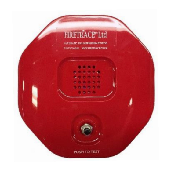
Page 3: System Overview
Self contained Alarm Sounder (FT0178). It is important that both the cylinder & Firetrace® tubing are correctly installed and that the system is subjected to a regular maintenance regime in line with BS5306-3 by a competent engineer. -
Page 4: System Layout
System Layout All our standard low pressure Firetrace® systems are supplied with all the necessary fixings for the Trace detection tube. Red trace detection tube – FT0115* End of Line Charging adapter – Optional Monitoring Pressure Switch FT0118 FT0124 Isolate... - Page 5 Firetrace® Installation Instructions. Cylinder When installing the Firetrace® system it is important that a suitable cylinder location is selected and that the cylinder is orientated correctly. The cylinder location shall be in a clean area away from direct heat. The cylinder must not be placed in a location where the ambient temperature is above 80 Degrees centigrade.
- Page 6 Firetrace® Automatic Detection Tubing The Firetrace® Automatic Detection tubing is the key part of the system and acts not only as the detector but also as the delivery method for the FE-36. The correct installation of the tubing is important to achieve optimum performance from the system.
- Page 7 Tube Fixings The Firetrace® Automatic Detection tubing is the key part of the system and acts not only as the detector but as the delivery method for the extinguishant as well. The correct installation of the tubing is important to achieve optimum performance from the system.
- Page 8 Tube bending radius The Firetrace® tubing acts as the detector and provides the delivery of the extinguishant. It is imperative that the tubing is not kinked or crushed and the following minimum bending radius must be adhered to. Should the tubing be kinked or damaged in anyway then the Firetrace® tubing must be replaced: FT0115 Firetrace®...
- Page 9 All compression fittings must be secured in the following manner: a) Cut the tube end ensuring the cut is clean and free from burrs. Check that no debris/ swarf is left in the tube. b) Place the nut over the end of the tube with its threaded section towards the end of the tube. c) Push the tube fully home into the body.
-
Page 10: Commissioning The System
Commissioning the System Warning Firetrace® cylinders contain 12 bar pressure This procedure shall be read in conjunction with system layout earlier in this booklet. Do not turn integrated isolate valve until system is fully commissioned (pressurised) Locate cylinder and firmly secure with bracket provided Remove black cap from the top of the cylinder. - Page 11 Firetrace® Pressure switch (FT0124 & FT0124/T75) Optional The optional Firetrace® pressure switch is used to monitor the system pressure and will activate in the event of a pressure drop. The switch can be introduced and removed from the cylinder whilst it is under pressure. This allows its operation to be proven both during commissioning and future servicing.
-
Page 12: Service And Maintenance
Service & Maintenance The Firetrace® systems can operate in a harsh environment and are occasionally subjected to high temperatures and extreme vibration. It is essential that the systems are regularly serviced to ensure their correct operation. In order to comply with British Standard BS 5306 (section three) the following maintenance tasks shall be carried out periodically. - Page 13 Firetrace® Limited recommend that all systems are fully serviced every 12 Months by a competent engineer If there’s no visible sign of pressure drop then; ✓ Check date of manufacture and record when discharge test is required .(10 years from New Date) ✓...
- Page 14 Address: Unit 22, Knightsdale Road, Ipswich, Suffolk. IP1 4JJ Telephone: 01473 744090 Facsimile: 01473 744901 Email: info@firetrace.co.uk Website: www.firetrace.co.uk Twitter: @firetrace_uk...
Need help?
Do you have a question about the Direct Systems and is the answer not in the manual?
Questions and answers