Table of Contents
Advertisement
Quick Links
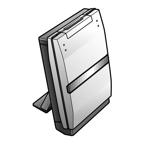
MINIDISC RECORDER
MJ-NS1
THIS MANUAL IS APPLICABLE TO THE FOLLOWING MODEL(S) AND TYPE(S).
Model
Type
MJ-NS1
ZPWXJ
¶ This product is a system(s) component.
This product does not function properly independently ; to avoid malfunctions, be
sure to connect it to the prescribed system component(s), otherwise damage may
result.
¶ Please connect it to the STEREO CD TUNER XC-NS1 and STEREO POWER AMPLI-
FIER M-NS1 for adjustment and operation inspection.
Component
STEREO CD TUNER
STEREO POWER AMPLIFIER
SPEAKER SYSTEM
MINIDISC RECORDER
CONTENTS
1. SAFETY INFORMATION ........................................... 2
2. EXPLODED VIEWS AND PARTS LIST ..................... 3
4. PCB CONNECTION DIAGRAM ............................... 21
5. PCB PARTS LIST .................................................... 26
6. ADJUSTMENT ......................................................... 29
PIONEER CORPORATION
PIONEER ELECTRONICS SERVICE, INC. P.O. Box 1760, Long Beach, CA 90801-1760, U.S.A.
PIONEER EUROPE NV Haven 1087, Keetberglaan 1, 9120 Melsele, Belgium
PIONEER ELECTRONICS ASIACENTRE PTE. LTD. 253 Alexandra Road, #04-01, Singapore 159936
c
PIONEER CORPORATION 2000
Power Requirement
DC power supplied from other system component
Model
XC-NS1
M-NS1
S-NS1-LRW
MJ-NS1
4-1, Meguro 1-chome, Meguro-ku, Tokyo 153-8654, Japan
Service manual
RRV2348 (RRV2341)
RRV2349 (RRV2321)
RRV2371
Except YPWXJ type
RRV2363
This manual.
7. GENERAL INFORMATION .................................. 37
7.1 DIAGNOSIS ................................................... 37
7.1.1 SINGLE OPERATION METHOD ............ 37
7.1.2 POWER ON SEQUENCE ....................... 38
7.1.3 DISASSEMBLY ....................................... 40
7.2 IC ................................................................... 43
8. PANEL FACILITIES AND SPECIFICATIONS ...... 46
ORDER NO.
RRV2363
Remarks
Remarks
T - ZZV AUG. 2000 Printed in Japan
Advertisement
Table of Contents

Related Manuals for Pioneer MJ-NS1


Summary of Contents for Pioneer MJ-NS1
-
Page 1: Table Of Contents
PIONEER CORPORATION 4-1, Meguro 1-chome, Meguro-ku, Tokyo 153-8654, Japan PIONEER ELECTRONICS SERVICE, INC. P.O. Box 1760, Long Beach, CA 90801-1760, U.S.A. PIONEER EUROPE NV Haven 1087, Keetberglaan 1, 9120 Melsele, Belgium PIONEER ELECTRONICS ASIACENTRE PTE. LTD. 253 Alexandra Road, #04-01, Singapore 159936 PIONEER CORPORATION 2000 T –... -
Page 2: Safety Information
“LOAD ” is low. ∗ Refer to page 30. IMPORTANT THIS PIONEER APPARATUS CONTAINS LASER OF CLASS 1. SERVICING OPERATION OF THE APPARATUS S H O U L D B E D O N E B Y A S P E C I A L L Y INSTRUTED PERSON. -
Page 3: Exploded Views And Parts List
MJ-NS1 2. EXPLODED VIEWS AND PARTS LIST • NOTES: Parts marked by "NSP" are generally unavailable because they are not in our Master Spare Parts List. • mark found on some component parts indicates the importance of the safety factor of the part. - Page 4 MJ-NS1 2.2 EXTERIOR 22(1/2) 22(2/2) " Refer to 2.3 MD Mechanism"...
- Page 5 MJ-NS1 EXTERIOR PARTS LIST Mark No. Description Part No. MAIN UNIT AWU7607 RELAY UNIT AWU7576 KEY L UNIT AWU7577 KEY R UNIT AWU7652 BLUE UNIT AWU7653 IC UNIT AWU7654 MD Mechanism AXA7087 Lead Card 30P (J4101) ADD7280 (MAIN CN4101 ↔ MD CORE CN104)
- Page 6 MJ-NS1 2.3 MD MECHANISM CN102 CN105 CN101 CN103...
- Page 7 MJ-NS1 MD MECHANISM PARTS LIST Mark No. Description Part No. Mark No. Description Part No. MD CORE MAIN UNIT AWU7591 S. Holder RNK2307 MD CORE SW UNIT AWU7592 Worm Wheel RNK2309 Lead Card 7P RDD1403 Hook (POM) RNK2310 Lead Wire 2P...
-
Page 8: Block Diagram And Schematic Diagram
MJ-NS1 3. BLOCK DIAGRAM AND SCHEMATIC DIAGRAM 3.1 BLOCK DIAGRAM (MD) (REC) CN104 MD CORE MAIN UNIT IC110 (AK4519VF) Audio Codec IC103 (MSM51V4400D70TSK) DRAM IC102 (LR376487) MD PICKUP Encoder/Decoder IC101 CN101 (RF) CONTROL (IR3R55M) Digital Servo RF Amp. IC107 (BD7910FV) - Page 9 MJ-NS1 Note : When ordering service parts, be sure to refer to "EXPLODED VIEWS and PARTS LIST" or "PCB PARTS LIST". DIGITAL IN To CD Receiver From Deck CN4103 JA4601 CN4102 12 13 10 15 12 13 10 15 IC4201...
-
Page 10: Overall Connection Diagram
MJ-NS1 3.2 OVERALL CONNECTION DIAGRAM IC UNIT (AWU7654) MD CORE MD CORE MAIN UNIT SW UNIT (AWU7591) (AWU7592) KEY-R UNIT (AWU7652) -
Page 11: Relay Unit
MJ-NS1 MAIN UNIT (AWU7607) KEY-L UNIT (AWU7577) BLUE UNIT RELAY UNIT (AWU7653) (AWU7576) - Page 12 MJ-NS1 3.3 MAIN UNIT (1/2) MAIN UNIT (1/2) (AWU7607) (REC) (MD) (MD) 3V-5V Converter (MD) : AUDIO SIGNAL ROUTE (MD) : DIGITAL SIGNAL ROUTE (REC) : AUDIO SIGNAL ROUTE (REC)
- Page 13 MJ-NS1 : The power supply is shown with the marked box. (MD) (REC) (MD) (MD) (MD) IC UNIT (AWU7654)
- Page 14 MJ-NS1 3.4 MAIN UNIT (2/2), KEY-R, KEY-L, RELAY and BLUE UNITS RELAY UNIT BLUE UNIT (AWU7576) (AWU7653) CN4901 J4904 KEY-L UNIT (AWU7577) SWITCHES S4901 : EJECT S4902 : REC J4907 J4908 TEST3 CN4107 KEY-R UNIT (AWU7652) TEST1 SWITCHES CN4105 S4903 : STOP...
- Page 15 MJ-NS1 MAIN UNIT (2/2) (AWU7607) SYSTEM CONTROL U-COM TEST2 CN4106...
-
Page 16: Head Driver
MJ-NS1 3.5 MD CORE MAIN and MD CORE SW UNITS MD CORE MAIN UNIT (AWU7591) (RF) (RF) (RF) (RF) RF AMP HEAD DRIVER (REC) (REC) (REC) (REC) (REC) MD PICKUP RWY1019 LOADING MOTOR ASSY REA1290 CARRIAGE MOTOR ASSY 5ch MOTOR DRIVER... -
Page 17: Audio Codec
MJ-NS1 : The power supply is shown with the marked box. (RF) : RF SIGNAL ROUTE : DIGITAL SIGNAL ROUTE (MD) : AUDIO SIGNAL ROUTE (MD) (REC) : AUDIO SIGNAL ROUTE (REC) (MD) (RF) (REC) ENC/DEC DIGITAL SERVO (CD) (REC) - Page 18 MJ-NS1 WAVEFOAM OF EACH PART Note : The number with indicate the each measuring point number of the schematic diagram. MD CORE MAIN UNIT IC101 - pin 35 (ADIPO) IC102 - pin 75 (FE MON) CN103 - pin 1 (SLD +)
- Page 19 MJ-NS1 IC102 - pin 74 (DADATA) IC110 - pin 11 (BCLK) MODE: PLAY (1kHz 0dB) MODE: PLAY (1kHz 0dB) DISC : TGYS1 or MMD-110 DISC : TGYS1 or MMD-110 V : DC1V/div. H : 0.2µsec/div. V : DC1V/div. H : 0.1µsec/div.
- Page 20 MJ-NS1 VOLTAGE OF EACH PART MD CORE MAIN UNIT (1kHz 0dB PLAY) IC101 IC102 IC103 IC104 IC105 IC108 IC109 Voltage Voltage Voltage Voltage Voltage Voltage Voltage Voltage Voltage Voltage 0.78 1.53 1.59 0.73 3.18 4.19 0.77 1.65 0.22 3.21 0.75 1.42...
-
Page 21: Pcb Connection Diagram
MJ-NS1 4. PCB CONNECTION DIAGRAM NOTE FOR PCB DIAGRAMS: 1. Part numbers in PCB diagrams match those in the schematic diagrams. 2. A comparison between the main parts of PCB and schematic diagrams is shown below. Symbol in PCB Symbol in Schematic... -
Page 22: Main Unit
MJ-NS1 4.1 MAIN , KEY-R ,KEY-L ,RELAY BLUE and IC UNITS MAIN UNIT IC4001 From IC4002 DECK CD TUNER CN104 (ANP7348-B) KEY-L UNIT (ANP7348-B) IC UNIT KEY-R UNIT (ANP7348-B) (ANP7348-B) RELAY UNIT BLUE UNIT (ANP7348-B) SIDE A... - Page 23 MJ-NS1 MAIN UNIT IC4203 IC4201 IC4202 IC4101 (ANP7348-B) KEY-L UNIT Q4103 (ANP7348-B) IC UNIT KEY-R UNIT (ANP7348-B) (ANP7348-B) RELAY UNIT BLUE UNIT (ANP7348-B) SIDE B (ANP7348-B)
- Page 24 MJ-NS1 4.2 MD CORE MAIN and MD CORE SW UNITS MD CORE MAIN UNIT IC108 Q102 Q101 IC104 IC103 IC102 IC106 IC101 (ANP7353-B) MD CORE SW UNIT (ANP7353-B) SIDE A...
- Page 25 MJ-NS1 LOADING CN4101 MOTOR ASSY REC HEAD MD CORE MAIN UNIT IC107 IC110 IC105 IC109 MD PICKUP (ANP7353-B) MD CORE SW UNIT (ANP7353-B) CARRIAGE SPINDLE MOTOR ASSY MOTOR SIDE B...
-
Page 26: Pcb Parts List
MJ-NS1 Mark No. Description Part No. Mark No. Description Part No. 5. PCB PARTS LIST • NOTES: Parts marked by "NSP" are generally unavailable because they are not in our Master Spare Parts List. • mark found on some component parts indicates the importance of the safety factor of the part. - Page 27 MJ-NS1 Mark No. Description Part No. Mark No. Description Part No. SWITCHES AND RELAYS MD CORE MAIN UNIT S4903,S4904 ASG7013 SEMICONDUCTORS RESISTORS IC110 AK4519VF All Resistors RS1/10S IC107 BD7910FV IC105 BR93LC56F OTHERS IC101 IR3R55M IC102 LR376487 5P Cable Holder 51048-0500...
- Page 28 MJ-NS1 Mark No. Description Part No. Mark No. Description Part No. C190,C197,C199,C204-C206 CKSQYF104Z25 C208,C210 CKSQYF104Z25 C119,C123-C126,C130,C132 CKSQYF105Z16 C134,C136,C138,C147,C164 CKSQYF105Z16 C177 CKSQYF105Z16 RESISTORS R111 RS1/8S270J Other Resistors RS1/10S OTHERS CN104 30P Connector RKN1039 X101 (33.8MHz) RSS1055 CN105 ZR Connector S2B-ZR-SM3A CN102...
-
Page 29: Adjustment
MJ-NS1 6. ADJUSTMENT 6.1 MD SECTION ADJUSTMENT Jigs and Measuring Instructions • Thermometer • Test Disc • Oscilloscope For servo system adjustment : GGF1328 (MMD-212) • Optical Power Meter For recording/playback inspection : GGF1328 (MMD-212), GGF1277 (or MMD-317) TGYS1 (or MMD-110), Commercial discs •... - Page 30 MJ-NS1 6.1.2 Test Mode Use the Remote Control Unit of Accessory or Service Remote Control Unit (GGF1067) at the Test Mode. Note1 : It is impossible to enter the Test Mode in the Single Operation Mode. Note2 : Unit Test Mode (U-TEST) is for inspection by the function checker of the production line.
- Page 31 MJ-NS1 6.1.3 MD Mechanism Assy Adjustment and Check 1 Temperature Check (Please perform this check soon after the power has been switched on.) Note: When IC101 (RF-AMP) or IC104 (mechanical controller) has been exchanged or when a correction changing VD+3 has been made, be sure to correctly perform all steps up to step 7.
- Page 32 MJ-NS1 3 Grating Adjustment Press the 0 (MD EJECT) key to take out the cartridge of Optical power meter in the state of step 7 of 2 , and then it is possible from steps 2 of this item. Step No.
- Page 33 MJ-NS1 4 Preliminary Adjustment It is possible from steps 3 of this item in the state of step 5 of 3 . Step No. Operation Keys and Operation Method FL Display Status Remarks In the Power ON state, selecting MD function,short the...
- Page 34 MJ-NS1 6 Defocus Adjustment It is possible from steps 3 of this item in the state of step 5 of 5 . Step No. Operation Keys and Operation Method FL Display Status Remarks In the Power ON state, selecting MD function,short the...
- Page 35 MJ-NS1 7 Jitter/C1 Error Check at the time of Playback Step No. Operation Keys and Operation Method FL Display Status Remarks In the Power ON state, selecting MD function,short the EJECT Test mode "MECHA TEST pin". LOADING Insert the test disc GGF1328 (MMD-212).
- Page 36 MJ-NS1 8 Jitter/C1 Error Check at the time of Recording/Playback FL Display Remarks Step No. Operation Keys and Operation Method Status In the Power ON state, selecting MD function,short the EJECT Test mode "MECHA TEST pin". LOADING Insert the test disc GGF1277 (or MMD-317).
-
Page 37: General Information
MJ-NS1 POWER SUPPLY POINT 7. GENERAL INFORMATION 7.1 DIAGNOSIS 7.1.1 SINGLE OPERATION MODE How to enter the single operation mode DC +9V 1. Supply DC power to CN4103 power supply pin of the MD MAIN UNIT. (Pin7 : +9V ,Pin8 : GND ,Pin9 : –9V) 2. -
Page 38: Power On Sequence
MJ-NS1 7.1.2 POWER ON SEQUENCE Outline • When MD mechanism is normal, an operation of MD is decided whether communication is done normally. When MD mechanism does not perform a correct operation, first confirm waveform of communication. (Refere to step 1.) •... - Page 39 MJ-NS1 3. Disc insertion and TOC READ User Insert a disc TOC READ System controller command issue Mech. controller EJECT END (NO DISC state) LOAD STOP TOC READ STOP (MD mech.) • System controller always grasps the state of MD mechanism.
-
Page 40: Disassembly
MJ-NS1 7.1.3 DISASSEMBLY Top Panel and MD Mechanism KEY-R UNIT Rear side KEY-L UNIT IND UNIT Mechanism Top Panel MD RELAY UNIT MAIN UNIT IC UNIT × 3 Go to MD Mechanism Assy MD Mechanism Assy • Removal of the MD Mechanism Assy 1 Remove a screw A. - Page 41 MJ-NS1 4 Shift part B to the position shown in the figure while raising the • Removal of the MD Pickup Under Slider. (At the same time, the Upper Slider moves to the 1 Remove the MD Head. (One screw A) front.)
- Page 42 MJ-NS1 • MD Pickup Installation • Removal of the Head Lifter Perform installation in reverse order of the removal. (Please use 1 Remove the Lifter SP. care as the MD Head mounting screw can be crushed easily. 2 Tilt the Head Lifter to the rear and push part A to disengage it.
- Page 43 MJ-NS1 7.2 IC • The information shown in the list is basic information and may not correspond exactly to that shown in the schematic diagrams. PDG257A [MAIN UNIT (2/2) : IC4101] • System Control U-COM FUCTION PIN NAME NOTE ACTIVE D.MUTE...
- Page 44 MJ-NS1 FUCTION PIN NAME NOTE ACTIVE PB5/SCK1PF4 D.CLK MD display communication clock output PB6/SI1 (NC) PB7/SO1 D.DATA MD display communication data output PE0/EC0 (to GND) PE1/EC1 (to GND) PE2/CINT (to GND) PE3/NM1 (to GND) PE4/PWM0 (NC) Take care to use also device test terminal...
- Page 45 MJ-NS1 AK4519VF [MD CORE MAIN UNIT : IC110] • Audio Codec IC...
-
Page 46: Panel Facilities And Specifications
MJ-NS1 8. PANEL FACILITIES AND SPECIFICATIONS Top Panel Front Panel 1. 6 – Press to play an MD, or pause one that's already 6. MD REC indicator – Lights up during record or record-pause playing (press again to restart playback). In record mode, mode. -
Page 47: Specifications
MJ-NS1 SPECIFICATIONS Recording method Magnetic field modulation overwritten type Playback method ..Non-contact optical type Sampling frequency 44.1KHz,32KHz,48KHz Frequency response ....20Hz – 20KHz Wow and flutter ....Limit of measurement (±0.001% W.PEAK) or less (EIAJ) Power requirements ........DC Dimensions .. - Page 48 PIONEER CORPORATION 4-1, Meguro 1-chome, Meguro-ku, Tokyo 153-8654, Japan PIONEER ELECTRONICS SERVICE, INC. P.O. Box 1760, Long Beach, CA 90801-1760, U.S.A. PIONEER EUROPE NV Haven 1087, Keetberglaan 1, 9120 Melsele, Belgium PIONEER ELECTRONICS ASIACENTRE PTE. LTD. 253 Alexandra Road, #04-01, Singapore 159936 PIONEER CORPORATION 2000 T –...
-
Page 49: Contrast Of Miscellaneous Parts
Screws adjacent to mark on product are used for disassembly. Reference Nos. indicate the pages and Nos. in the service manual for the base model. CONTRAST TABLE MJ-NS1/ZPW/DF and MJ-NS1/ZPWXJ are constructed the same except for the following: Part No. Ref. Mark...
Need help?
Do you have a question about the MJ-NS1 and is the answer not in the manual?
Questions and answers