Table of Contents
Advertisement
Quick Links
Advertisement
Table of Contents

Related Manuals for Epever LFP5.42KWH51.2V-P65F2QT50


Summary of Contents for Epever LFP5.42KWH51.2V-P65F2QT50
- Page 1 LiFePO4 (LFP) Battery Product manual LFP5.42KWH51.2V-P65F2QT50...
-
Page 2: Table Of Contents
Contents 1 Important Safety Instructions ..........1 2 General Information ..............3 2.1 Appearance ....................... 3 2.2 Product size ...................... 4 3 Basic Information ..............5 3.1 Interface definition ................... 5 3.2 Product features ....................6 3.3 LCD color display .....................7 4 Instructions ................. 10 4.1 Packing list ......................10 4.2 Installation requirements ................ -
Page 3: Important Safety Instructions
1 Important Safety Instructions ※ Thank you for choosing EPEVER Lithium Iron Phosphate (LFP) battery, please read this manual carefully before using this product. ※ It is strictly forbidden to install this product in harsh environments such as moisture, salt spray, corrosion, greasy, flammable and explosive, or a large amount of dust accumulation. - Page 4 d) It is forbidden to heat and incinerate batteries. It may melt battery components, lose safety features, or burn electrolyte. Overheating can deform, heat, smoke, or burn the battery. Emergency treatment method a) When the electrolyte leaks, avoid skin and eye contact with the electrolyte. In case of contact, wash immediately with plenty of water and seek help from a doctor.
-
Page 5: General Information
2 General Information 2.1 Appearance Side Front Side Black LCD color screen Wall mounting bracket B&I Metal handle Grounding screw interface Negative connector Negative connector Positive connector Positive connector Inverter communication interface PC upper computer communication interface Parallel communication interface Parallel communication interface Weak-current switch Pressure reducing valve... -
Page 6: Product Size
2.2 Product size... -
Page 7: Basic Information
3 Basic Information 3.1 Interface definition (1) The RS232 communication interface pin are defined as follows, and the RJ11 communication interface is used to connect the upper computer of the lithium battery PC. RJ11 Pin RJ11 Definition 1、2、6 ( RJ11) (2) The pins of the CAN/RS485 communication interface are defined as follows, and the RJ45 communication interface is used for the communication connection between the lithium battery and the inverter host. -
Page 8: Product Features
(4) The BMS communication interface pins are defined as follows, and the RJ45 communication interface is used for the communication connection between lithium battery and lithium battery parallel machine. Pin No RJ45 Definition RS485-B RS485-A UP-IN RS485-A (RJ45 ) RS485-B 3.2 Product features ... -
Page 9: Lcd Color Display
3.3 LCD color display Interface introduction:: Main state page Icon Introduction: Main Menu Icon: Tap to enter the main menu HOME interface Main State Icon: Click to enter the Main State interface Parallel Data Icon: Click to enter the Parallel Data page HOME page ... - Page 10 Menu ② Menu SOC(Total) Current Voltage Main BMS INFO state Warranty page Current Parallel data Voltage BMS info Cell 01 voltage Cell 02 voltage Voltage ....Cell 16 voltage PACK Info Temperature Mos-T ENV-T Warning Home Protect BMS Status Fault Record GOOD WE PROTOCOL LV BMS Protocol (CAN) for Solar...
- Page 11 Growatt BMS CAN_Bus-protocol-low-voltage USER-485-voltron Voltronic Inverter and BMS 485 communication protocol 20200325 RS485 PYLON RS 485-protocol-pylon-low-voltag Luxpowertek Battery Protocol RS 485-V English Language select Chinese (Traditional Chinese) System PACK SN (BLUETOOTH SN ) Note: The protocol list is access from the BMS motherboard. The following is an example: Based on the built-in list of each BMS motherboard, the first time you change the protocol, you need to enter the permission password, and the initial password is 123456.
-
Page 12: Instructions
4 Instructions 4.1 Packing list Before unpacking, please check the outside of the battery for damage to the packaging and check the model of the battery. If there is any abnormality, please do not open the package and contact the after-sales service center as soon as possible. -
Page 13: Installation Requirements
4.2 Installation requirements a. Space installation distance Master and check the performance of all tools and devices to ensure safety before using them. The left and right distance between battery packs is recommended. Minimize the distance as much as possible. - Page 14 b. Installation environment The battery works best at 20~40°C. Avoid installation in environments with direct high temperature and rain. Avoid installation close to high temperature heat source or low temperature cold source. Avoid installation in places where the ambient temperature changes drastically. ...
- Page 15 d. Space installation requirements 1. Make the mounting bracket close to the wall (level correction), mark the screw holes with a marker, and then remove the mounting bracket. 2. Use a hammer drill to drill a hole in the wall (diameter:10mm, depth: 65mm), insert the M8 expansion screw and tighten it.
-
Page 16: Wiring Diagram
e. Wiring diagram Positive output power cable (1500mm) Negative output power cable (1500mm) RS485 communication cable (1500mm) Lithium battery positive parallel power cable Lithium battery negative parallel power cable Lithium battery parallel communication cable(DIP~BMS) (1200mm) - Page 17 Positive output power cable (1500mm) Negative output power cable (1500mm) RS485 communication cable (1500mm) Warning 1. For operational safety and compliance, please disconnect the communication and cable link with the inverter when storing the battery. 2. During the handling and installation of the battery, it is recommended to wear safety helmets, goggles, protective shoes and other safety equipment suitable for the work to prevent accidental injury;...
-
Page 18: Charging Operation
4.3 Charging operation Check before charging. Inspect the appearance of the battery and inverter or other connected equipment to ensure that the power cord and all wiring harnesses are connected. Make sure the power supply meets the specification requirements for the battery. 2. -
Page 19: Description Of Battery Parallel Capacity And Voltage
4.5 Description of battery parallel capacity and voltage Maximum Discharge cut-off Number of battery Capacity charging voltage voltage parallel groups 212Ah 2 groups 57.6V 41.6V 318Ah 3 groups 57.6V 41.6V 424Ah 4 groups 57.6V 41.6V 530AH 5 groups 57.6V 41.6V 636Ah 6 groups 57.6V... -
Page 20: Protection Features
5 Protection Features Item Factory default parameter Set state Postscript Cell overcharge 3600mV settable alarm voltage Cell Cell overcharge overcharge 3650mV settable protection voltage protection Cell overcharge 1.0S settable protection delay Cell overcharge Cell 3380mV settable protection voltage over-voltage SOC<96% protection SOC release settable... - Page 21 Battery over-discharge 44.8V settable alarm voltage Battery Overall over-discharge 43.2V settable over-discharge protection voltage protection Battery over-discharge 1.0S settable protection voltage delay Battery Battery over-discharge 47.2V settable over-discharge protection release protection voltage release Release on charge Plug in the charger to activate Charging over-current alarm 105A...
- Page 22 Discharge over-current 1 1.0S settable Protection delay Discharge Automatic Automatically disconnects after 1 minute over-current 1 disconnect protection Charge disconnect Discharge current > 1A release Discharge Protection current settable It can be set 10 >150A consecutive over-current 2 Protection delay 500mS settable occurrences to lock...
- Page 23 Charging high 65℃ temperature settable protection Charge high 55℃ temperature settable protection release Discharge low -15℃ settable temperature alarm Low temperature -20℃ discharge settable protection Discharge low -15℃ temperature settable protection release High discharge 65℃ settable temperature alarm Discharge high 70℃...
- Page 24 Ambient high 75℃ temperature settable protection Ambient high 65℃ temperature settable protection release Low battery Low battery alarm No alarm when SOC<5% settable alarm condition charging Sleep voltage 3150mV settable Sleep function Delay time 5min settable Charging and Cell voltage voltage difference>1V settable discharging are not...
-
Page 25: Specifications
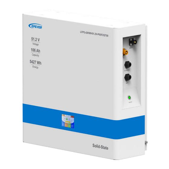
6 Specifications LFP5.42KWH51.2V-P65F2QT50 Parameter LiFePO Battery Type 51.2V Nominal Voltage 106Ah Nominal Capacity 5427Wh Energy Continuous Discharge Current 57.6V Charge Cut-off Voltage 41.6V Discharge Cut-off Voltage Maximum Charge Current 100A@30min Maximum Discharge Current 120A@10S Peak Discharge Current Recommend Discharge Current 50.88~53.6V... -
Page 26: Precautions
7 Precautions 7.1 Maintenance precautions Item Cycle If the battery is not in use, it needs to be fully charged 3 months and discharged to 50%. Check whether the wall bracket installation is loose. 6 months Please tighten the appropriate position if available. Check the casing for damage. -
Page 27: Disclaimers
8 Disclaimers The warranty does not apply to the following conditions: Damage caused by improper use or inappropriate environments (It is strictly forbidden to install the Energy Storage System in the humid, salt spray, corrosive, greasy, flammable, explosive, dust accumulative or other harsh environments). - Page 28 HUIZHOU EPEVER TECHNOLOGY CO., LTD BeiJing Service Hotline:010-82894896/82894112 Huizhou Service Hotline:0752-3889706 Shenzhen Service Hotline:0755-89236770 E-mail:sales@epever.com Website:www.epever.com.cn...
Need help?
Do you have a question about the LFP5.42KWH51.2V-P65F2QT50 and is the answer not in the manual?
Questions and answers