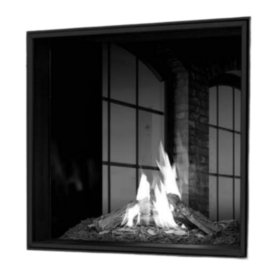
Table of Contents
Advertisement
Quick Links
WARNING: If the information in this manual is not followed exactly, a fire or
explosion may result causing property damage, personal injury or loss of life.
Installation and service must be performed by a qualified installer, service agency or
the gas supplier.
C#4001609
U33I
U33I
Double sided Glass Installation kit
Double sided Glass Installation kit
50- 4167
50- 4167
CERTIFIED TO: ANSI Z21.88 / CSA 2.33 VENTED GAS FIREPLACE HEATERS
CSA 2.17 GAS FIRED APPLIANCES FOR HIGH ALTITUDES
| 1
C-16964C
Advertisement
Table of Contents

Summary of Contents for Sherwood Industries Urbana U33I
- Page 1 U33I U33I Double sided Glass Installation kit Double sided Glass Installation kit 50- 4167 50- 4167 WARNING: If the information in this manual is not followed exactly, a fire or explosion may result causing property damage, personal injury or loss of life. Installation and service must be performed by a qualified installer, service agency or the gas supplier.
-
Page 2: Table Of Contents
Contents Kit Contents ..........3 CSS Heat Release . -
Page 3: Kit Contents
Kit Contents KIT CONTENTS 1) T20 Fasteners 2) Hand knobs 3) Left and Right 4)Clean Face Trim Glass bumbers 6)Tiling Trim 6) Steel Stud 7) Rear cabinet 8) Glass Clamps 9) GLASS 10) Instruction Manual 11) safety Screen 12) safety screen trim... - Page 4 Combustible Header on outside MANDATORY 19.00 of enclosure NON COMBUSTIBLE CEILING Heat release opening OPENING Steel Stud ceiling clearance (Provided in kit) 5.00 5.00 5.00 20” Minimum 20” non combustible board CSS Minimum Framing Clearances The U33 can be used with or without a cool surface system. When activated the cool surface system allows for the minimum chase width to be reduced.
-
Page 5: Css Heat Release
S Heat Release 17” (432mm) Valance False Ceiling False Ceiling 3" Minimum 4" 76mm 102mm " 17” (432mm) 121mm 17 " 3" 1" 6" Minimum 76mm 25mm 152mm 121mm Maximum Minimum Minimum Minimum A valance may be desired If your ceiling dimension is to accentuate or hide the greater than the minimum outlet. -
Page 6: Activating Cool Surface System (Css)
Attach the heat shield to the top of the cabinet. face the heat shield to the wall you will have the opening (This is relevant when the unit has Activating CSS been converted to double sided installation. The U33 comes from the Factory in NON CSS configuration. to convert your unit to CSS Ready you need to. -
Page 7: Non Css Minimum Framing
Non CSS Minimum framing MANDATORY NON COMBUSTIBLE CEILING ceiling clearance Steel Stud (Provided in kit) Minimum 20” non combustible board 20” Double Sided Minimum Framing Clearances The above dimensions represent theminimum size required for the safe operation of the unit. Please note that these dimensions mean that the unit would not be centred within the chase. -
Page 8: Preparing For Install
Preparing For Install The Rear of the firebox needs to be removed from the unit. This is a heavy item so it is reccomended to remove the rear liners first before attempting to remove the rear of the firebox to do this; Remove Safety Screen, Lift up the frame of the screen and pull the screen towards you. -
Page 9: Preparing For Install
Preparing For Install The removable liners are held on with hooks. To remove, locate the correct panel, slide the liner up and then remove from firebox. A screwdriver may be required to gently slide the panel up. Behind the removable panel you will see T20 fasteners, remove these screw to release the liner from the firebox. -
Page 10: Rear Cabinet Removal
Rear Cabinet Removal T20 DRIVER Remove the clamps securing the insulation board. then remove the board itself. T20 DRIVER Unscrew and remove the cabinet back. 7/16” RATCHET/SOCKET Unbolt the x4 clamps securing the liner pocket in place. 10 |... -
Page 11: Liner Pocket - Clamp Removal
Liner Pocket - Clamp Removal Remove the liner pocket T20 DRIVER Remove the alignment pins in all 4 corners of the opening T20 DRIVER Install both the left and right glass bumpers at the bottom of the opening. use the T20 fasteners provided. NOTE Ensure you install the correct bracket for the left and right hand side of the unit. -
Page 12: Installing Glass Clamps
Installing glass clamps arrange the clamps so that the gasket will be touching Install the 4 glass clamps. Make sure that the braided gasket will be touching the glass and not steel. use the provided hand knobs. Keep the clamps loose and move the clamps out of the way to ensure the easy install of the glass. -
Page 13: Installing Cabinet
Installing Cabinet T20 DRIVER Install framing pockets to the the unit, using T20 fasteners. Ensure that the screen catches on the inside of the vertical pockets are situated towards the top of the unit. Your Unit comes with 2 different types of tiling trim a Straight, clean edge &... -
Page 14: Installing Screen
Installing Screen T20 DRIVER Attach trim to safety screen. start with the bottom trim first. then attach left and right trims, ensuring that the hooks are facing out on the Unit, rotate the screen hooks into place. do this on both the left and right hand side. - Page 15 Installing Screen Rotate screen into place making sure the hooks attach to the unit securing the screen in place. MANUFACTURED BY: SHERWOOD INDUSTRIES LTD. 6782 OLDFIELD RD. SAANICHTON, BC, CANADA V8M 2A3 www.urbanafireplaces.com November 2023 C-16964 | 15...


Need help?
Do you have a question about the Urbana U33I and is the answer not in the manual?
Questions and answers