
Related Manuals for Attila DIGITAL


Summary of Contents for Attila DIGITAL
- Page 1 ATTILA ® BLAST CHILLER TRANSLATION OF THE ORIGINAL INSTRUCTIONS DIGITAL | TOUCH | ALADINO Revision 02 - 03/2024 USE AND MAINTENANCE MANUAL...
-
Page 3: Table Of Contents
1.5. Warranty ............7 8.3.1. Temperature measurement ......34 2. SAFETY WARNINGS ........8 8.3.2. Blasting times ..........34 8.4. Use of “Digital” version blast chiller ....36 2.1. Obligations and prohibitions ....... 9 8.4.1. Activation ............. 36 2.1.1. Obligations ............. 9 8.4.2. - Page 4 10.2.3. Door gasket replacement ........ 55 11. DIAGNOSTICS ........56 11.1. Alarms ............56 11.1.1. “Digital” version blast chiller alarms ....56 11.1.2. “Touch” version blast chiller alarms ....57 11.1.3. 'ALADINO' version blast chiller alarms ..... 60 12. DECOMMISSIONING AND DISPOSAL ..61 12.1.
-
Page 5: Use And Maintenance Manual
USE AND MAINTENANCE MANUAL ATTILA USE AND MAINTENANCE MANUAL... -
Page 6: General Preliminary Information
Carefully read this manual before carrying out installation, maintenance and/or before using the equipment. This manual is attached to the equipment ATTILA - DIGITAL | TOUCH | ALADINO. The Manufacturer is not liable for breakages, accidents or various problems due to non-compliance with and in any case the non-application of the provisions contained in this manual. -
Page 7: Regulatory Framework
USE AND MAINTENANCE MANUAL ATTILA 1.4. REGULATORY FRAMEWORK The equipment is designed according to the regulatory framework described in the accompanying declaration of conformity and the identification plate placed on the same, as well as the requirements, which can be downloaded directly from the manufacturer’s website. -
Page 8: Safety Warnings
ATTILA SAFETY WARNINGS The Manufacturer cannot be held liable for any damage, suffered by people or things, caused by non-compliance with the aforementioned requirements or deriving from tampering with even a single part of the equipment and from the use of non-original spare parts. -
Page 9: Obligations And Prohibitions
USE AND MAINTENANCE MANUAL ATTILA Only use original spare parts. It is strictly forbidden to make changes to the equipment. Do not start the equipment with wet hands or when there is contact with water. 2.1. OBLIGATIONS AND PROHIBITIONS 2.1.1. -
Page 10: Identification And Description
ATTILA IDENTIFICATION AND DESCRIPTION 3.1. EQUIPMENT IDENTIFICATION The nameplate is on the rear of the equipment. Contains: ▪ Serial number ▪ The type/functional features ▪ The details of the certification and marking. Do not remove the identification plate and/or replace it with other plates. -
Page 11: Intended Use
USE AND MAINTENANCE MANUAL ATTILA 3.2. INTENDED USE The equipment is a BLAST CHILLER for professional use. It enables previously cooked food products to be cooled rapidly. It works in the following modes: ▪ Positive blasting = up to +10°C/ +3°C ▪... -
Page 12: Main Components
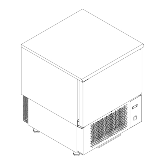
ATTILA 3.4. MAIN COMPONENTS POS. ELEMENT NOTES STRUCTURE CONTROL PANEL DOOR WITH HANDLE SHELF SHELF SUPPORT REMOVABLE CONDENSATE DRIP TRAY Including: ▪ EVAPORATOR UNIT ▪ Resistor FEET Including: ▪ Compressor REFRIGERATING UNIT ▪ Condenser ▪ CORE PROBE CHAMBER TEMPERATURE PROBE... -
Page 13: Receipt And Handling
USE AND MAINTENANCE MANUAL ATTILA RECEIPT AND HANDLING 4.1. EQUIPMENT RECEIPT The equipment is delivered on a pallet packed in strapped cardboard. Upon delivery, check that the packaging is intact and that it has not been damaged during transport. 4.1.1. -
Page 14: Packaging Removal And Inspection
ATTILA 4.1.2. PACKAGING REMOVAL AND INSPECTION For the removal of the packaging: STEP ACTION PICTURE Remove the straps. Remove the packaging cardboard. Togliere l’imballo in cartone; Sganciare le protezioni in plastica dei piedini; Lift the equipment to remove it from the pallet. -
Page 15: Packaging Disposal
USE AND MAINTENANCE MANUAL ATTILA 4.1.3. PACKAGING DISPOSAL The materials used for packaging are recyclable and must be collected. Separate the various packaging materials and dispose of them in accordance with the regulations in force in the country of installation. -
Page 16: Handling Operations
ATTILA 4.2.2. HANDLING OPERATIONS Carefully read the instructions before moving the equipment. Only qualified technical personnel should perform handling operations on the equipment. The manufacturer accepts no liability in the event of non-compliance with current safety regulations. Move the equipment while keeping it upright at all times. Do not tilt the equipment. -
Page 17: Installation
USE AND MAINTENANCE MANUAL ATTILA INSTALLATION Only qualified technical personnel should perform installation operations on the equipment. The manufacturer accepts no liability in the event of non-compliance with current safety regulations. Do not install and use the equipment in ATEX classified environments, locations or areas. -
Page 18: Minimum Safety Distances
ATTILA 5.1.2. MINIMUM SAFETY DISTANCES In order to ensure proper functioning of the equipment and thus proper air circulation, observe the minimum safety distances from side walls, other equipment and/or heat sources. MINIMUM SAFETY DISTANCES Side / Rear / Upper... -
Page 19: Positioning And Adjustment Of Feet
USE AND MAINTENANCE MANUAL ATTILA 5.2. POSITIONING AND ADJUSTMENT OF FEET Position the equipment perfectly level, so that it can work properly, the condensation water from the defrosting process can drain off correctly and there are no noisy vibrations of the motor. -
Page 20: Connections
ATTILA CONNECTIONS 6.1. ELECTRICAL CONNECTION Only qualified technical personnel should perform connection operations on the equipment. The electrical connection must be carried out in accordance with the legal compendium and regulations applicable in the country where the equipment is installed. -
Page 21: Control Panel
USE AND MAINTENANCE MANUAL ATTILA CONTROL PANEL 7.1. “DIGITAL” VERSION BLAST CHILLER INTERFACE POS. ICON ELEMENT DESCRIPTION ▪ Set to “0”: machine switched off MAIN SWITCH 0/I ▪ Set to “I”: machine electrically powered. DISPLAY Displays the equipment operating parameters. -
Page 22: Alarms
ATTILA POS. ICON ELEMENT DESCRIPTION Press and release Time from start of Blasting cycle selection (+3°C or -18°C). cycle/ Function and Press for at least 4 sec cycle selector The panel goes into Stand-by mode. Press and release Start / Stop / Freezing Selected cycle start/stop. -
Page 23: Cycle-Dependent Interface Characteristics
USE AND MAINTENANCE MANUAL ATTILA 7.1.2. CYCLE-DEPENDENT INTERFACE CHARACTERISTICS The commands on the interface take on characteristics depending on the operating cycle of the equipment. STOPPING PHASE The display shows the time (in hours and minutes) if a time cycle is selected, or the temperature of the core probe in °C for a probe cycle. -
Page 24: Touch" Version Blast Chiller Interface - Ewbc800
ATTILA 7.2. “TOUCH” VERSION BLAST CHILLER INTERFACE - EWBC800 POS. ICON ELEMENT DESCRIPTION ▪ Set to “0”: machine switched off MAIN SWITCH 0/I ▪ Set to “I”: machine electrically powered. DISPLAY Displays the equipment operating parameters. Press and release in stop status Allows you to select a cycle: ▪... - Page 25 USE AND MAINTENANCE MANUAL ATTILA POS. ICON ELEMENT DESCRIPTION Press and release in stop status Allows you to select a cycle: ▪ TARGET KEY Timed ▪ With core probe. Depending on the selection, the corresponding LED lights up. Press and release in stop status...
- Page 26 ATTILA POS. ICON ELEMENT DESCRIPTION Press and release in stop status Selects the function: ▪ Defrosting (parameter dEF) ▪ Manual storage (parameter Con) ▪ Cell light (parameter LMP). ESC KEY Press and release in parameter configuration Confirms the displayed parameter value.
-
Page 27: Display
USE AND MAINTENANCE MANUAL ATTILA 7.2.1. DISPLAY POS. ICON ELEMENT DESCRIPTION DISPLAY Steady on Active compressor. COMPRESSOR LED Compressor off. Steady on Defrosting in progress. Flashing DEFROSTING LED Defrosting requested but not in progress. Defrosting deactivated. Steady on Evaporator cell fan on. - Page 28 ATTILA POS. ICON ELEMENT DESCRIPTION TEMPERATURE Steady on DISPLAY IN °F Automatic programme in progress, temperature display in °F. Steady on AUX LED Sterilisation function (if present) or heating probe (if present) in progress. TEMPERATURE Steady on DISPLAY IN °C...
-
Page 29: Aladino' Version Blast Chiller Interface
USE AND MAINTENANCE MANUAL ATTILA 7.3. 'ALADINO' VERSION BLAST CHILLER INTERFACE POS. ICON ELEMENT DESCRIPTION ▪ Set to “0”: machine switched off MAIN SWITCH 0/I ▪ Set to “I”: machine electrically powered. DISPLAY Displays the equipment operating parameters. Time adjustment - /... -
Page 30: Display
ATTILA 7.3.1. DISPLAY POS. ICON DESCRIPTION Displays the equipment operating parameters. Indicates that the temperature is expressed in degrees Celsius or Fahrenheit Indicates the current time Indicates that the equipment is powered, but in Standby Steady light indicates that core blasting is active. -
Page 31: Display - Messages
USE AND MAINTENANCE MANUAL ATTILA POS. ICON DESCRIPTION Steady on Active maintenance cycle Flashing current displayed time represents the current duration of the maintenance cycle Indicates that an alarm is active (both blocking and non-blocking) 7.3.2. DISPLAY - MESSAGES MESSAGE... -
Page 32: Use
ATTILA Before using the equipment, check that it is in perfect condition. In the presence of faults, the equipment must be decommissioned and the Technical Assistance Service must be contacted. CAUTION Keep all the supply and return air ventilation openings inside the equipment free of obstructions. -
Page 33: Product Load To Be Blasted
USE AND MAINTENANCE MANUAL ATTILA 8.2. PRODUCT LOAD TO BE BLASTED Load a maximum of 15 kg on each shelf. The load must be evenly distributed on the shelf. Pre-cool the chamber before starting the positive and negative blasting cycle. -
Page 34: Product Blasting
ATTILA 8.3. PRODUCT BLASTING The following is purely indicative. The responsibility for blasting processes lies solely with the user of the equipment, who must comply with the local regulations and Good Practice Manuals (GHP) applicable by him/her. The Manufacturer is not liable for damage to property or persons. - Page 35 USE AND MAINTENANCE MANUAL ATTILA MAXIMUM PRODUCT FOOD BLASTING TIME CYCLE USED LOAD THICKNESS FIRST COURSES Béchamel 4 cm 70 minutes POSITIVE Meat broth 6-7 cm 90 minutes POSITIVE Baked cannelloni 4 Kg 3-4 cm 40 minutes POSITIVE Vegetable minestrone...
-
Page 36: Use Of "Digital" Version Blast Chiller
ATTILA 8.4. USE OF “DIGITAL” VERSION BLAST CHILLER 8.4.1. ACTIVATION Do not start the equipment with wet hands or when there is contact with water. STEP ACTION PICTURE Press the O/I main switch. Note: when switched on, the button lights up green. -
Page 37: Blasting Cycle With Core Probe
USE AND MAINTENANCE MANUAL ATTILA 8.4.3. BLASTING CYCLE WITH CORE PROBE If, when starting a probe blasting, the error “PnS” appears after 5 minutes, reposition the probe in a more suitable way. Alternatively, the blasting will continue in timed mode. -
Page 38: Timed Blasting Cycle
ATTILA 8.4.4. TIMED BLASTING CYCLE To carry out the timed blasting cycle: STEP ACTION Press the O/I main switch. Press the button and select the standard temperature +3°C or -18°C. Press the keys to set the desired time for the blasting cycle. -
Page 39: Adjusting Operating Parameters
, while the number is displayed, to switch to the next/previous parameter. Press again to change the selected parameter. Note: to change the parameter, use the buttons (refer to the table below). For the parameter list, please refer to “Digital version blast chiller parameters”. -
Page 40: Use Of "Touch" Version Blast Chiller
ATTILA 8.5. USE OF “TOUCH” VERSION BLAST CHILLER 8.5.1. ACTIVATION Do not start the equipment with wet hands or when there is contact with water. STEP ACTION PICTURE Press the O/I main switch. Note: when switched on, the button lights up green. -
Page 41: Blasting Cycle With Core Probe
USE AND MAINTENANCE MANUAL ATTILA 8.5.3. BLASTING CYCLE WITH CORE PROBE To carry out the blasting cycle with core probe: STEP ACTION Press the button and select the core probe target. Press the button repeatedly to display the maximum cycle duration timeout. -
Page 42: Timed Blasting Cycle
ATTILA 8.5.4. TIMED BLASTING CYCLE To carry out the timed blasting cycle: STEP ACTION Press and select the time target. Press the button repeatedly to display the cycle duration. Note: Within 3 seconds use to change the time. Note: To reset the blasting cycle target to the default value, press the button three times. -
Page 43: Manual Storage Cycle
USE AND MAINTENANCE MANUAL ATTILA 8.5.5. MANUAL STORAGE CYCLE To perform the manual storage cycle: STEP ACTION Press the button and select the manual storage function (Parameter Con). Press the button and select positive (+3°C) or negative (-18°C) storage mode. -
Page 44: Cell Sterilisation Cycle (If Any)
ATTILA 8.5.6. CELL STERILISATION CYCLE (IF ANY) To activate a sterilisation cycle, close the equipment door. If the door is opened during the sterilisation cycle, the cycle stops. To sterilise the cell: STEP ACTION Press the button and select the cell sterilisation function (Parameter StE). -
Page 45: Cell Light (If Any)
USE AND MAINTENANCE MANUAL ATTILA 8.5.8. CELL LIGHT (IF ANY) To switch the cell light on or off: STEP ACTION Press the button and select the cell light function (Parameter LMP). Press the button to switch the cell light on or off. -
Page 46: Automatic Defrost
ATTILA 8.5.10. AUTOMATIC DEFROST The equipment is equipped with an automatic system for daily defrosting set by the Manufacturer. Act on the control panel to change the automatic defrosting (number, duration, interval). Remove the drain plug before defrosting. 8.5.11. ADJUSTING OPERATING PARAMETERS The equipment has two types of parameters: ▪... -
Page 47: Password Entry For Advanced Parameters
USE AND MAINTENANCE MANUAL ATTILA 8.5.12. PASSWORD ENTRY FOR ADVANCED PARAMETERS Access to advanced parameters is restricted to qualified personnel only. For access to advanced parameters: STEP ACTION Press and hold the buttons simultaneously to access the parameter list. Press and select parameter PA2. -
Page 48: Use Of 'Aladino' Version Blast Chiller
ATTILA 8.6. USE OF 'ALADINO' VERSION BLAST CHILLER 8.6.1. ACTIVATION Do not start the equipment with wet hands or when there is contact with water. STEP ACTION PICTURE Press the O/I main switch. Note: when switched on, the button lights up green. -
Page 49: Positive Cycle (+3°C) / Negative (-18°C) / Deep Negative (-35°C)
USE AND MAINTENANCE MANUAL ATTILA 8.6.3. POSITIVE CYCLE (+3°C) / NEGATIVE (-18°C) / DEEP NEGATIVE (-35°C) To perform the positive/negative/deep negative cycle: STEP ACTION Press to activate the mode to be used. Note: The equipment starts a 10" countdown at the end of which the blast chilling phase starts in temperature mode. -
Page 50: Infinite Negative Cycle (-40°C)
ATTILA 8.6.4. INFINITE NEGATIVE CYCLE (-40°C) To perform the infinite negative cycle: STEP ACTION Press the button. Note: The equipment starts a 10" countdown after which the blast chilling phase begins. Press during the countdown phase to change the selection of the blast chilling type. -
Page 51: Adjusting Operating Parameters
USE AND MAINTENANCE MANUAL ATTILA 8.6.6. ADJUSTING OPERATING PARAMETERS The equipment has two types of parameters: ▪ Basic, user-oriented parameters ▪ Advanced, password-protected parameters for qualified personnel. For adjusting the operating parameters of the equipment, via control panel: STEP ACTION Press and hold buttons simultaneously for 4"... -
Page 52: Cleaning
ATTILA CLEANING 9.1. CLEANING SAFETY WARNINGS WARNING Electrical hazard. Disconnect the power supply before cleaning. WARNING Electrical hazard. Do not use water jets and/or high-pressure lances to wash the internal and external parts of the equipment. WARNING Do not damage the refrigerant fluid circuit. -
Page 53: Table Of Cleaning Operations
USE AND MAINTENANCE MANUAL ATTILA 9.2. TABLE OF CLEANING OPERATIONS The table lists a number of cleaning operations to be performed according to the recommended schedule. FREQUENCY OPERATION EVERY 6 WHEN DAILY MONTHLY YEARLY REQUIRED MONTHS ■ Cleaning accessible internal parts ■... -
Page 54: 10. Maintenance
ATTILA MAINTENANCE WARNING Electrical hazard. Disconnect the power supply before carrying out maintenance work. Only authorised technical personnel should service the equipment. 10.1. ROUTINE MAINTENANCE Ensure smooth operation over time of the equipment by performing periodic/preventive checks and maintenance. 10.1.1. -
Page 55: Extraordinary Maintenance
USE AND MAINTENANCE MANUAL ATTILA 10.2. EXTRAORDINARY MAINTENANCE Extraordinary maintenance includes service, repair, and restoration of nominal operating conditions or replacement of a faulty, defective or worn component. 10.2.1. REPLACEMENT OF MOTOR FAN For replacement, contact the Authorised Dealer or Service Centre. -
Page 56: Diagnostics
ATTILA DIAGNOSTICS 11.1. ALARMS 11.1.1. “DIGITAL” VERSION BLAST CHILLER ALARMS MESSAGE CAUSE TYPE OF ERROR SOLUTIONS If the wire is disconnected, Check that all terminal Generic or internal probe reinsert it into the terminal board wires are plugged in. error. -
Page 57: Touch" Version Blast Chiller Alarms
USE AND MAINTENANCE MANUAL ATTILA 11.1.2. “TOUCH” VERSION BLAST CHILLER ALARMS MESSAGE CAUSE EFFECT TYPE OF ERROR SOLUTIONS Core probe not Check the connection If an automatic properly connected. of the core probe to the programme is running, Core probe error. - Page 58 ATTILA MESSAGE CAUSE EFFECT TYPE OF ERROR SOLUTIONS Check the connection Condenser probe not of the auxiliary probe to connected correctly. the EWBC800. Condenser probe error. Condenser probe Replace the auxiliary failure. probe. Check the connection cable between base and communication keyboard.
- Page 59 USE AND MAINTENANCE MANUAL ATTILA MESSAGE CAUSE EFFECT TYPE OF ERROR SOLUTIONS Close the blast chiller door to reactivate the evaporator cell fan (if The programme or Open door (function of parameter SLd=0). function is running. parameter tdO). While the programme Deactivation of cell fan.
-
Page 60: Aladino' Version Blast Chiller Alarms
ATTILA 11.1.3. 'ALADINO' VERSION BLAST CHILLER ALARMS MESSAGE CAUSE TYPE OF ERROR SOLUTIONS If the wire is disconnected, Check that all terminal board wires Pr 1 Chamber probe error. reinsert it into the terminal are plugged in. and tighten the screw. -
Page 61: Decommissioning And Disposal
USE AND MAINTENANCE MANUAL ATTILA DECOMMISSIONING AND DISPOSAL 12.1. LONG PERIODS OF INACTIVITY If the equipment is not used for a long period of time (more than 2-3 weeks): STEP ACTION Disconnect the power supply. Carry out a thorough cleaning of the equipment (see chapter 'CLEANING'). -
Page 62: Attachments
ATTILA ATTACHMENTS 13.1. WIRING DIAGRAM 13.1.1. ATT03, ATT05, ATT07, ATT10, ATT10P S-CO U.-3 U.-2 U.-1 MICROPORTA X.-4 X.-3 X.-2 BA56-12EWA X.-1 1 2 3 4 5 6 7 CUT THE BRIDGE 1 2 3 4 ONLY 10 TRAYS 05/03/2018 09:29:43... -
Page 63: Att3_Th, Att5_Th, Att7_Th, Att10_Th, Att10P_Th
USE AND MAINTENANCE MANUAL ATTILA 13.1.2. ATT3_TH, ATT5_TH, ATT7_TH, ATT10_TH, ATT10P_TH 1 2 3 4 ONLY 10 TRAYS 16/04/2018 19:19:21 Sheet:... -
Page 64: Att15, Att20
ATTILA 13.1.3. ATT15, ATT20... -
Page 65: Att15_Th, Att20_Th
USE AND MAINTENANCE MANUAL ATTILA 13.1.4. ATT15_TH, ATT20_TH... -
Page 66: Att03_Ea, Att05_Ea, Att10_Ea
ATTILA 13.1.5. ATT03_EA, ATT05_EA, ATT10_EA... -
Page 67: Parameters
USE AND MAINTENANCE MANUAL ATTILA 13.2. PARAMETERS 13.2.1. “DIGITAL” VERSION BLAST CHILLER PARAMETERS PARAMETER DESCRIPTION Def.4R Def.3R When switching to storage The buzzer sounds for indicated sec. Door Presence ▪ 0=Door absent ▪ 1=Door present. Fan in blasting ▪ 0= in parallel with the compressor ▪... - Page 68 ATTILA PARAMETER DESCRIPTION Def.4R Def.3R Chamber Set for positive storage. °C Chamber Set for negative storage. °C Positive timed blasting duration. Negative timed blasting duration. Condenser temperature set, for secondary fan. °C Enabling 2nd condenser fan. Configuration relay 4 ▪...
-
Page 69: Touch" Version Blast Chiller Basic Parameters
USE AND MAINTENANCE MANUAL ATTILA 13.2.2. “TOUCH” VERSION BLAST CHILLER BASIC PARAMETERS PARAMETER 3/5T 15/20T DESCRIPTION Timed positive blasting duration (timeout for automatic programme). Parameter visible without password. Timed negative blasting duration (timeout for automatic programme). Parameter visible without password. -
Page 70: Touch" Version Blast Chiller Advanced Parameters
ATTILA 13.2.3. “TOUCH” VERSION BLAST CHILLER ADVANCED PARAMETERS Access to advanced parameters is password-protected and restricted to qualified personnel only PARAMETER 3/5T 15/20T DESCRIPTION C° Chamber temperature hysteresis (differential). C° Chamber Set for positive blasting. C° Chamber Set for negative blasting. - Page 71 = Defrosting ▪ EF = Evaporator fan ▪ CMP = Compressor. flag Digital output configuration R2. Similar to Fr1. flag Digital output configuration R3. Similar to Fr1. flag Digital output configuration R4. Similar to Fr1. flag Digital output configuration R5. Similar to Fr1.
- Page 72 ATTILA PARAMETER 3/5T 15/20T DESCRIPTION Stop utilities with open door ▪ flag CF = Stop compressor and fans ▪ Fan = Stop fans only. C° Set sterilisation temperature. Maximum Core heating duration. C° Set Core heating temperature. Set start temperature 2nd condenser fan.
-
Page 73: Aladino' Version Blast Chiller Parameters
USE AND MAINTENANCE MANUAL ATTILA 13.2.4. 'ALADINO' VERSION BLAST CHILLER PARAMETERS SIC - Safety R455a/ PARAMETER DESCRIPTION R290 R452a Entering passwords to access protected menus Display in °C (0) or °F (1) Display Language ( 0 - Ita, 1 - Eng, 2 - Fra ) Programme 3 - Pin setpoint [°C]... - Page 74 ATTILA R455a/ PARAMETER DESCRIPTION R290 R452a Programme 1 - Maximum compressor on time 9999 before reaching setpoint [Minutes] Programme 1 - Timed blast chilling duration in hours Programme 1 - Timed blast chilling duration in minutes Programme 1 - Core blasting timeout hours...
- Page 75 USE AND MAINTENANCE MANUAL ATTILA R455a/ PARAMETER DESCRIPTION R290 R452a Programme 4 - Pin setpoint [°C] °C Programme 4 - Chamber setpoint (delta on pin) [°C] °C Programme 4 - Chamber setpoint maintenance °C (delta on pin) [°C] Programme 4 - Maximum compressor on time...
- Page 76 StandBy [ 0 - disabled, 1 - for Stop, 2 - with fan, 3 - with resistor, 4 - with fan and resistor ] Chamber temperature detection probe selection Defrost end temperature [0.1°C] 0.1°C Maximum defrosting function time [min] dl - Digital input management R455a/ PARAMETER DESCRIPTION R290 R452a...
- Page 77 Display Format (0 - Easy, 1 - Advanced) Number of displays Digital input function ( 0 - Disabled, 3 - Door open ) Relay function 1 ( 0 - None, 1 - Compressor, 2 - Wait compressor start, 3 - Evaporator, 4 - Condenser,...
Need help?
Do you have a question about the DIGITAL and is the answer not in the manual?
Questions and answers