Table of Contents
Advertisement
Quick Links
Advertisement
Table of Contents

Subscribe to Our Youtube Channel
Related Manuals for Cisco TelePresence MSE 8000


Summary of Contents for Cisco TelePresence MSE 8000
- Page 1 Cisco TelePresence MSE 8000 Getting started 61-0004-07...
-
Page 2: Table Of Contents
Contents General information ........................ 3 About the MSE 8000 series ..................3 Package contents ......................3 Required tools ......................4 Hardware features ........................5 The front of the chassis ..................... 5 The rear of the chassis ....................6 The fan trays ........................8 Alarms ...........................10 Installing the MSE 8000 chassis ..................12 Before you start ......................12... -
Page 3: General Information
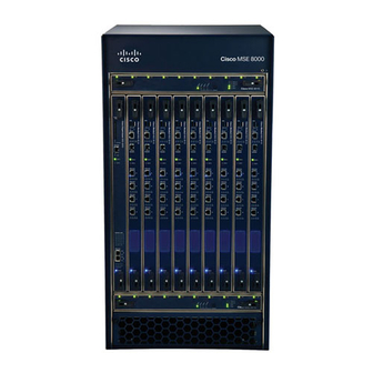
General information About the Cisco TelePresence MSE 8000 The Cisco TelePresence MSE 8000 (Media Services Engine) is a carrier-class video and audio conferencing chassis that delivers many times the throughput of existing solutions. Designed for large scale video communication, the MSE 8000 chassis supports up to 10 blades and over 1 gigabit per second of audio and video conferencing. -
Page 4: Required Tools
General information Required tools Table 1: Tools required for MSE 8000 installation and servicing Installation Installing MSE 8000 chassis Connecting protective earth Connecting DC power Installing fan trays Installing blades Servicing Replacing a fan tray ... -
Page 5: Hardware Features
Hardware features Hardware features The front of the chassis Figure 1 shows the chassis as it looks before you install any blades or fan trays. Figure 1: The empty chassis Upper Fan Tray Slot ESD Grounding Socket (marked with symbol Blade Slots Lower Fan Tray Slot Air Filter Door... -
Page 6: The Rear Of The Chassis
Hardware features The rear of the chassis Figure 2 shows the position of features on the rear of the chassis. Figure 2: The rear of the chassis Air Exhaust Input/Output Panel B (reserved for future expansion) Supervisor A Input/Output Panel DC Power Terminal A DC Power Terminal B Cable Support Bracket... - Page 7 Hardware features DC power terminals The MSE 8000 requires a -48V DC to -60V DC power supply. There are two pairs of DC power terminals at the rear of the chassis, protected by a transparent cover. Supervisor A input/output panel Supervisor A input/output panel provides connections to the MSE 8000 Supervisor.
-
Page 8: The Fan Trays
Hardware features The fan trays The MSE 8000 has two fan trays. Refer to Installing the fan trays on page 14 for the installation procedure. If you are replacing a faulty fan tray, refer to Replacing a fan tray on page 31. Figure 4 shows the features of the fan tray and the location of the LED indicators. - Page 9 Hardware features Table 2 describes the function of the blade status indicators. Table 3 describes the function of the chassis status indicators. Table 4 describes the function of the alarm indicators. Table 2: Blade status indicators Color Indicates Green A blade is installed in this slot and is functioning correctly The blade in this slot has an alarm condition associated with it Where no blade is installed in a slot, both blade indicators for that slot are extinguished.
-
Page 10: Alarms
Hardware features Table 4: Alarm indicators Color Indicates Status Green System status is normal Minor Amber An alarm of the specified severity is active, or has occurred in the past and has not been cleared: Major : Alarm is active ... - Page 11 Hardware features connector; three of these are for minor, major and critical alarm outputs. The remaining relay is a dedicated power alarm that activates when the power fails or the Supervisor is removed. The pinout for the alarm connector can be found on page 33 on the Supervisor’s web interface ...
-
Page 12: Installing The Mse 8000 Chassis
Note that additional rack mounting ears are available from Cisco. Ensure the stabilizing arms of the rack are fully extended and the rack is secured to the floor and/or ceiling. -
Page 13: Step Two: Ground The Chassis
Installing the MSE 8000 chassis Step two: Ground the chassis Connect a protective earth cable (not supplied) to the protective earth terminals on the rear of the chassis. Tighten the bolts with a 10mm A/F socket to a torque of 4Nm (35 inch pounds). -
Page 14: Installing Fan Trays And Blades Into The Mse 8000
Before installing the fan trays and blades into the MSE 8000, read the safety information for this product at: http://www.cisco.com/go/telepresence/safety. When servicing or removing components or connections, first attach an anti-static wrist strap with a banana plug connection to the ESD grounding socket provided on the top front of the unit. - Page 15 Installing fan trays and blades into the MSE 8000 Figure 6: Inserting the fan tray into the slot Figure 7: Closing the retaining latches on the front of the fan tray...
-
Page 16: Installing The Blades
Installing fan trays and blades into the MSE 8000 Installing the blades You must install either a blade or a blanking blade in each of the ten slots in the chassis. The Supervisor blade must be installed into slot 1 of the MSE 8000 chassis. - Page 17 Installing fan trays and blades into the MSE 8000 Figure 9: Closing the retaining latches on the front of a blade...
-
Page 18: Powering The Mse 8000
The MSE 8000 requires DC power in the range -48V to -60V nominal (refer to ratings). If DC within this range is available at your facility, refer to Connecting DC power to the MSE 8000 on page 23. Otherwise, use Cisco-supplied AC to DC power shelves as described in the following section. - Page 19 Powering the MSE 8000 The MSE 8000 will operate correctly with only one AC to DC power shelf. However, Cisco recommends using two power shelves each with an independent AC input for maximum redundancy. Figure 10 shows two power shelves each with two rectifier modules.
- Page 20 Each power shelf is supplied with one red and one black power cable which you should connect as described below: The color coding of DC power cables is not generally standardized. Cisco supplies one black and one red cable with each power shelf. Unless national or local regulations apply, assign these to the -VDC and RTN connections according to usual practice at your facility.
- Page 21 Before connecting an AC power shelf to the MSE 8000, you must read the documentation provided by the power shelf manufacturer. Figure 12 shows how to connect the Cisco supplied DC power cables to the power shelf. Figure 12: Connecting the DC power cables to the power shelf...
- Page 22 Powering the MSE 8000 Step three: AC to DC power shelf serial connections The Supervisor input/output panels on the rear of the MSE 8000 chassis each provide two serial ports. These serial ports enable the Supervisor to monitor the power shelves. The two serial ports for Supervisor A connect to the Supervisor blade in slot 1.
-
Page 23: Connecting Dc Power To The Mse 8000
Powering the MSE 8000 Connecting DC power to the MSE 8000 Before connecting power to the MSE 8000, ensure that: The chassis is connected to protective earth as described on page 13 There is a circuit breaker in each power supply conductor that is correctly rated ... - Page 24 Powering the MSE 8000 Connecting the power cables to the MSE 8000 The MSE 8000 will operate correctly with only one DC power feed. However, Cisco recommends using independent power feeds to the A and B inputs for maximum redundancy. Connect DC power cables as shown in Figure 13.
- Page 25 Powering the MSE 8000 To connect DC power cables to the MSE 8000: Using a TORX T20 screwdriver, remove the four screws that secure the transparent cover at the rear of the chassis; remove the transparent cover. Using the same screwdriver, attach the cable-support bracket to the rear of the MSE 8000, directly beneath the DC power terminals, using the four supplied screws.
-
Page 26: Installing Port And Screen Licenses
The license keys are provided in the accompanying paper document. Contact your reseller to get additional copies of these keys. Port and screen licenses are provided by Cisco so that you can increase the number of ports that are licensed without requiring new hardware (up to the maximum available on a particular blade type). -
Page 27: Allocating Port And Screen Licenses On The Supervisor Blade
Installing port and screen licenses Repeat steps 3 and 4 for every license key that is detailed on the attached document. Allocating port and screen licenses on the Supervisor blade Go to Port licenses Click on the link for the type of port license that you want to allocate. All the Allocation pages have the same layout irrespective of port license type. -
Page 28: Service Information
Service information Service information Hot-swap operations The following items can be removed and installed with the power connected to the MSE 8000 and are considered user-serviceable parts: blades fan trays air filter power supply rectifiers Although blades are hot-swappable parts, you must only remove one blade at any time. -
Page 29: Esd Protection
Service information ESD protection When servicing or removing components or connections, first attach an anti-static wrist strap with a banana plug connection to the ESD grounding socket provided on the top front of the unit as shown in Figure 15. Figure 15: Attaching an anti-static wrist strap... -
Page 30: Replacing The Air Filter
Cisco recommends an air filter inspection every month. A kit of four air filters is available from Cisco. This is a year’s supply in normal environments. The air filter replacement is a hot-swap operation to be performed by service personnel only. -
Page 31: Replacing A Fan Tray
Service information Replacing a fan tray If you open the retaining latches of a fan tray when power is connected to the MSE 8000, wait 20 seconds for the fans to slow before sliding out the fan tray. Never remove both fan trays from the MSE 8000 at the same time. If you remove a fan tray, replace it immediately. -
Page 32: Technical Specifications
Technical specifications Technical specifications Power requirements Table 6: MSE 8000 ratings Rating Value Nominal supply voltage range -48V DC to -60V DC Operating supply voltage limits -40.8V DC to -72V DC Maximum input current per cable 85A at -48V DC Circuit breaker (NEC requirement) 125A Circuit breaker (other than NEC) -
Page 33: Pinouts And Ratings For Alarm Connectors
Technical specifications Pinouts and ratings for alarm connectors The alarm connectors are DB15 male connectors. Table 8 provides pinout information for the alarm connectors: Table 8: Alarm connector pinout Description Minor alarm reset + Minor alarm reset - Major alarm reset + Major alarm reset - Critical alarm —... - Page 34 Technical specifications Notes: Alarm outputs and reset inputs are isolated from ground The power alarm is active when power to the chassis fails All alarms will activate if the Supervisor fails or is absent Table 9 provides alarm connector ratings: Table 9: Alarm connector ratings Rating Value...
-
Page 35: Pinouts For Rear Input/Output Serial Connectors
Technical specifications Pinouts for rear input/output serial connectors Table 10 provides pinout information for the rear input/output serial connectors: Table 10: Pinouts for rear I/O serial connectors Function Not connected Receive Transmit Signal ground Not connected Shell Chassis ground Notes for Table 10: Hardware flow control is not implemented ... -
Page 36: Troubleshooting And Technical Support Information
. Do not change the capture filter topic level Errors, warnings and information without the guidance of technical support. Getting more help Cisco recommends registering your product at http://www.tandberg.com/ services/video-conferencing-product-registration.jsp in order to receive notifications about the latest software and security updates. New feature and maintenance releases are published regularly, and we recommend that the MSE 8000’s software is always kept up to date. -
Page 37: Disclaimers And Notices
THIS MANUAL, EVEN IF CISCO OR ITS SUPPLIERS HAVE BEEN ADVISED OF THE POSSIBILITY OF SUCH DAMAGES. Cisco and the Cisco Logo are trademarks of Cisco Systems, Inc. and/or its affiliates in the U.S. www.cisco.com/go/ and other countries. A listing of Cisco's trademarks can be found at trademarks .
Need help?
Do you have a question about the TelePresence MSE 8000 and is the answer not in the manual?
Questions and answers