Table of Contents
Advertisement
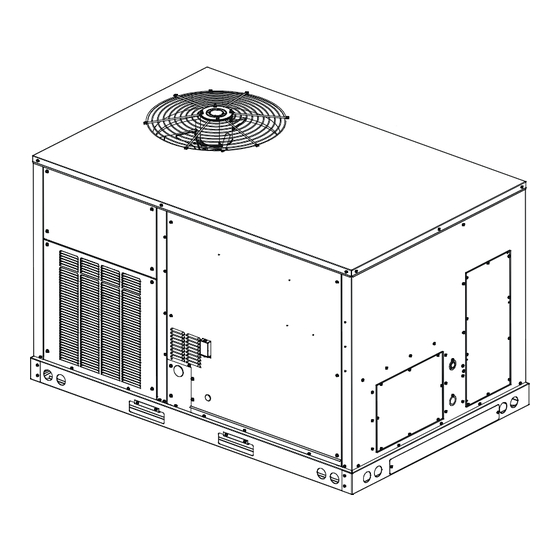
Packaged Gas / Electric Unit 3-6 Ton Direct Drive
High Efficiency Light Commercial DHG Models
Installation Instructions
This forced air central unit design complies with
requirements embodied in The American National Standard
/ National Standard of Canada ANSI Z21.47•CSA-2.3 Gas-
fired central furnaces.
NOTE: This equipment is only approved for use with
R-32 refrigerant.
©2024
IOD-1075
08/2024
Our continuing commitment to quality products may mean a change in specifications without notice.
19001 Kermier Rd., Waller, TX 77484
ONLY PERSONNEL THAT HAVE BEEN TRAINED TO INSTALL,
ADJUST, SERVICE, MAINTENANCE OR REPAIR
(HEREINAFTER, "SERVICE") THE EQUIPMENT SPECIFIED IN
THIS MANUAL SHOULD SERVICE THE EQUIPMENT.
THIS EQUIPMENT IS NOT INTENDED FOR USE BY
PERSONS (INCLUDING CHILDREN) WITH REDUCED
PHYSICAL, SENSORY OR MENTAL CAPABILITIES, OR
LACK OF EXPERIENCE AND KNOWLEDGE, UNLESS THEY
HAVE BEEN GIVEN SUPERVISION OR INSTRUCTION
CONCERNING USE OF THE APPLIANCE BY A PERSON
RESPONSIBLE FOR THEIR SAFETY.
CHILDREN SHOULD BE SUPERVISED TO ENSURE THAT
THEY DO NOT PLAY WITH THE EQUIPMENT.
THE MANUFACTURER WILL NOT BE RESPONSIBLE FOR
ANY INJURY OR PROPERTY DAMAGE ARISING FROM
IMPROPER SUPERVISION, SERVICE OR SERVICE
PROCEDURES. IF YOU SERVICE THIS UNIT, YOU ASSUME
RESPONSIBILITY FOR ANY INJURY OR PROPERTY
DAMAGE WHICH MAY RESULT. IN ADDITION, IN
JURISDICTIONS THAT REQUIRE ONE OR MORE LICENSES
TO SERVICE THE EQUIPMENT SPECIFIED IN THIS
MANUAL, ONLY LICENSED PERSONNEL SHOULD
SERVICE THE EQUIPMENT. IMPROPER SUPERVISION,
INSTALLATION, ADJUSTMENT, SERVICING, MAINTENANCE
OR REPAIR OF THE EQUIPMENT SPECIFIED IN THIS
MANUAL, OR ATTEMPTING TO INSTALL, ADJUST, SERVICE
OR REPAIR THE EQUIPMENT SPECIFIED IN THIS MANUAL
WITHOUT PROPER SUPERVISION OR TRAINING MAY
RESULT IN PRODUCT DAMAGE, PROPERTY DAMAGE,
PERSONAL INJURY OR DEATH.
DO NOT BYPASS SAFETY DEVICES
www.daikincomfort.com
INSTALLATION INSTRUCTIONS
WARNING
WARNING
Advertisement
Table of Contents

Related Manuals for Daikin DHG


Summary of Contents for Daikin DHG
- Page 1 INSTALLATION INSTRUCTIONS Packaged Gas / Electric Unit 3-6 Ton Direct Drive High Efficiency Light Commercial DHG Models Installation Instructions WARNING ONLY PERSONNEL THAT HAVE BEEN TRAINED TO INSTALL, ADJUST, SERVICE, MAINTENANCE OR REPAIR (HEREINAFTER, “SERVICE”) THE EQUIPMENT SPECIFIED IN THIS MANUAL SHOULD SERVICE THE EQUIPMENT.
-
Page 2: Table Of Contents
INDEX SAFETY INSTRUCTIONS RECOGNIZE THIS SYMBOL Safety Instructions............2 AS A SAFETY PRECAUTION Replacement Parts............4 General information............4 These installation instructions cover the outdoor Clearances...............8 installation of single package heating and cooling units. Roof Curb Post-Installation checks......8 See the Light Commercial Accessories Brochure for Roof Top Duct Connections..........8 information regarding accessories. -
Page 3: High Voltage
WARNING WARNING To prevent the risk of property damage, This unit must not be used as a “construction personal injury, or death, do not store heater” during the finishing phases of combustible materials or use gasoline or other construction on a new structure. This type of flammable liquids or vapors in the vicinity of use may result in premature failure of the unit this appliance. -
Page 4: Replacement Parts
Specification sheets can be found at Los equipos ó aparatos que producen monóxido de carbono www.daikincomfort.com for Daikin brand products. Within (tal como automóvil, calentador de gas, calentador de agua por medio de gas, etc) no deben ser operados en áreas cerradas debido al riesgo the website, please select the light commercial products de envenenamiento por monóxido de... - Page 5 EPA Regulations 3. In case of concealed damage, the carrier should be Important: The United States Environmental Protection notified as soon as possible-preferably within 5 days. Agency (EPA) has issued various regulations regarding 4. File the claim with the following supporting the introduction and disposal of refrigerants in documents: this unit.
-
Page 6: All Installations
If a leak is suspected, all naked flames shall be removed/ NOTE: Appliance is shipped from factory for vertical duct application. extinguished. If a leakage of refrigerant is found which requires brazing, Proper installation of the unit ensures trouble-free all of the refrigerant shall be recovered from the system. operation. -
Page 7: Roof Top Installations Only
Roof top Installations Only: responsibility of the installing contractor. All required • To avoid possible property damage or personal injury, hardware necessary for the assembly of the sheet metal the roof must have sufficient structural strength to curb is included in the curb accessory. carry the weight of the unit(s) and snow or water loads as required by local codes. -
Page 8: Clearances
NOTE: If the 36” minimum clearance is used on the control panel side of a DHG unit, a flue Flexible duct connectors between the unit and ducts are extension kit needs to be installed to prevent flue recommended. -
Page 9: Rigging Details
Removal is accomplished by extracting the The numbers may slightly vary depending on installed options. sheet metal retainers and pulling the struts through DHG Weights Table the base of the unit. Refer to rigging label on the unit. CAUTION... -
Page 10: Electrical Wiring
Bring condenser end of unit into alignment with the curb WARNING first. Lower unit carefully onto roof mounting curb. When a rectangular cantilever curb is used, care should be taken to Do not operate the compressor(s) without the center the unit. Check for proper alignment and orientation terminal plug fully engaged or the terminal cover of supply and return openings with duct. - Page 11 NOTE: Never operate the compressor in a vacuum or in reverse operation. CAUTION To prevent improper and dangerous operation CAUTION due to wiring errors, label all wires prior to disconnection when servicing controls. Verify To prevent damage to the wiring, protect wiring proper operation after servicing.
-
Page 12: Low Voltage Control Wiring
HIGH VOLTAGE ENTRANCE NOTE: CHECK TRANSFORMER (REMOVE PLUG) TO MATCH THE CORRECT VOLTAGE TAP WITH LINE VOLTAGE GROUND - LUG 19-3/8 31-3/8 LINE IN VOLTAGE L1, L2, L3 POWER SUPPLY LOW VOLTAGE ENTRANCE GROUND THERMOSTAT WIRE THERMOSTAT WIRE RETURN Gas DDC Control Box Note: Depending on the options installed, the 4-1/16 DIA. -
Page 13: Gas Supply Piping
NOTE: Refer to unit wiring diagrams for Piping thermostat or remote sensor connections. IMPORTANT NOTE: To avoid possible unsatisfactory operation or equipment damage due to under GAS SUPPLY PIPING firing of equipment, do not undersize the natural/ propane gas piping from the meter/tank to the unit. When sizing a trunk line, include all appliances on that line that could be operated simultaneously. -
Page 14: Proper Piping Practice
• Listed gas appliance connectors used in Gas Piping Checks accordance with the terms of their listing CAUTION that are completely in the same room as the equipment. Always use a new listed connector. • In the prior two methods above the connector To prevent property damage or personal injury or tubing must be protected from physical due to fire, the following instructions must... - Page 15 IMPORTANT NOTE: Propane gas conversion kits A manual gas shut off valve must be field installed external must be installed to convert units to propane gas. to the roof top unit. In addition, a drip leg must be installed NOx screens must be removed before converting near the inlet connection.
-
Page 16: Circulating Air And Filters
CONDENSATE DRAIN CONNECTION 6. All pipe connections should be sealed with a pipe thread compound, which is resistant to the fuel used with the furnace. A soapy water solution should be Condensate Drain Connection used to check all joints for leaks. A tap is located A 3/4”... -
Page 17: Startup, Adjustments, And Checks
STARTUP, ADJUSTMENTS, AND CHECKS The Startup, Adjustments, and Checks procedure provides a step-by-step sequence which, if followed, will assure the proper startup of the equipment in the minimum amount of WARNING time. Air balancing of duct system is not considered part of this procedure. -
Page 18: Air Flow Adjustments
Filter Section Check Standard Static Drive Motor Remove filter section access panels and check that filters Adjust the CFM for the unit by changing the position of are properly installed. Note airflow arrows on filter frames. the low voltage leads on the terminal block TB1. Refer to Appendix A for blower performance at each speed tap. -
Page 19: Gas System Check
Gas piping downstream from the unit inlet should be checked for leaks during the DHG Model wiring (Standard Static & High Static) subsequent sequence check. The supply gas pressure should be adjusted to 7.0” w.c. -
Page 20: Inlet Gas Pressure
Gas Supply And Manifold Check IGNITION ELECTRODE Gas supply pressure and manifold pressure with the FLAME SENSOR burners operating must be as specified on the rating plate. Gas Inlet Pressure Check Gas inlet pressure must be checked and adjusted in accordance to the type of fuel being consumed. - Page 21 3. To set low fire rate, open disconnect switch and remove jumper from R to W2. To set low fire manifold pressure, repeat steps above. Refer to Figure in gas input check section for location of high and low stage pressure adjustment.
-
Page 22: Normal Sequence Of Operation
This unit has one (RS) Manual Reset Limit Control Switch. CAUTION Check the limit to make sure it has not tripped. The limit may arrive at the job site tripped as a result of shipping To prevent unreliable operation or equipment shock. -
Page 23: Unit Shutdown
Heating (ULN Only) Automatic Reset High Limit Control (LS) This unit is equipped with an ignition control that Located in the burner compartment on the heat exchanger, automatically lights the main burner. DO NOT attempt to its sensing element projects through the blower section light the main burners by any other method. -
Page 24: Start-Up Procedure And Checklist
If subcooling and superheat are low, adjust TXV Zone controller must be powered through a Daikin Zoning/ superheat, then check subcooling. Accessory PCB to ensure that the Zoning Dampers open... - Page 25 6. Slowly lower the cooling temperature until the unit 1. If the compressor is operating backward, disconnect starts. The compressor, blower and fan should now the unit power supply and lock it in the “OFF” position. be operating. Allow the unit to run 10 minutes, make Switch two leads of the power supply at the unit sure cool air is being supplied by the unit.
-
Page 26: Maintenance
MAINTENANCE 4. Check for blockage of condensate drain. 5. Check power and control voltages. WARNING 6. Check running amperage. 7. Check operating temperatures and pressures. 8. Check and adjust temperature and pressure controls. ELECTRICAL SHOCK, FIRE OR EXPLOSION HAZARD 9. Check and adjust damper linkages. Failure to follow safety warnings exactly could 10. -
Page 27: Charging Procedures
Recovery IMPORTANT NOTE: Refer to the standing pressure test/leak detection method referenced later in When removing refrigerant from a system, either for servicing or decommissioning, it is recommended good this manual. practice that all refrigerants are removed safely. When transferring refrigerant into cylinders, ensure NOTE: ”Earthing”... -
Page 28: Troubleshooting
NOTE: Periodic observation of the flame and a Internal Control Failure log of C0 measurements are recommended. This If the integrated ignition control in this unit encounters an will aid in determining whether the furnace is internal fault, it will go into a “hard” lockout and turn off the operating efficiently or if the furnace requires diagnostic LED. - Page 29 • Check flame sensor Fault Recall (ULN Only) A drop in flame signal can be caused by nearly invisible The ignition control is equipped with a momentary push- coating on the sensor. Remove the sensor and carefully button switch that can be used to display on the diagnostic clean with steel wool.
- Page 30 Pressure Sensor (ULN Only) Low Flame Signal (ULN Only) The pressure sensor is mounted in the control box and Under some conditions, the fuel or air supply can create a connected to the induced draft blower. Its function is nearly invisible coating on the flame sensor. This coating to regulate the induced draft blower’s speed in order acts as an insulator causing a drop in the flame signal.
- Page 31 Abnormal Operation - Cooling Codes SHORT CYCLE COMPRESSOR DELAY (6 FLASH CODE) The automatic ignition control has a built-in feature that prevents damage to the compressor in short cycling situations. In the event of intermittent power losses or intermittent thermostat operation, the ignition control will delay output to the compressor contactor for three minutes from the time power is restored.
- Page 32 LED Flashing Codes table. REFRIGERANT SENSORS for REFRIGERANT DETECTION SYSTEMS shall only be replaced with sensors specified by the manufacturer. If REFRIGERANT SENSOR requires replacement, please replace with Sensata R32 Sensor PN#RGD-00ML12 (Daikin PN#SER2A08011). LED STATUS MODE LED FLASHING PATTERN...
- Page 33 TROUBLESHOOTING CODE LED TROUBLESHOOT STATUS MODE DEFINITION LED FLASHING PATTERN RECOMMENDED ACTIONS NOTES Slow LED flashing pattern Normal Operation No faults to report. No actions needed. (2 seconds on and 2 seconds off) A technician will need to find where the refrigerant leak In terms of the controls, no action is needed.
-
Page 36: Accessory Installation
THE FOLLOWING INSTRUCTIONS ARE MANDATORY FOR A2L SYSTEMS AND SUPERSEDE OTHER INSTRUCTIONS WARNING ONLY BRAZING TECHNIQUES AND APPROVED MECHANICAL JOINTS SHOULD BE USED TO CONNECT REFRIGERANT TUBING CONNECTIONS. NON-APPROVED MECHANICAL CONNECTORS AND OTHER METHODS ARE NOT PERMITTED IN THIS SYSTEM CONTAINING A2L REFRIGERANT. APPROVED MECHANICAL JOINTS WILL BE DETAILED IN THE PRODUCT'S SPECIFICATION SHEETS. - Page 37 ALTITUDE ADJUSTMENT FACTOR TO CALCULATE MINIMUM ROOM AREA The Indoor equipment mitigation requirements are calculated at sea level. For higher altitudes adjust the minimum room area specified on or near the Serial Plate by the corresponding altitude adjustment factor shown below. This table is provided as a reference. Adjusted room area (A ) is the product of the minimum room area specified in the serial plate and the min adj...
-
Page 38: Appendix A Blower Performance Tables
APPENDIX A BLOWER PERFORMANCE DATA 3 Ton 3 Ton Models: DHG0361D and DHG0363D Models: DHG0361D and DHG0363D Standard Static Drive Standard Static Drive Burners High Fire Input: 45,000 BTU/HR Burners High Fire Input: 70,000 BTU/HR Downflow Horizontal Downflow Horizontal Speed External Speed External... - Page 39 APPENDIX A BLOWER PERFORMANCE DATA 3 Ton 4 Ton Models: DHG0361D and DHG0363D Models: DHG0481D and DHG0483D Standard Static Drive Standard Static Drive Burners High Fire Input: 115,000 BTU/HR Burners High Fire Input: 70,000 BTU/HR Downflow Horizontal Downflow Horizontal Speed External Speed External...
- Page 40 APPENDIX A BLOWER PERFORMANCE DATA 4 Ton 4 Ton Models: DHG0481D and DHG0483D Models: DHG0481D and DHG0483D Standard Static Drive Standard Static Drive Burners High Fire Input: 115,000 BTU/HR Burners High Fire Input: 140,000 BTU/HR Downflow Horizontal Downflow Horizontal S peed E xternal S peed E xternal...
- Page 41 APPENDIX A BLOWER PERFORMANCE DATA 5 Ton 5 Ton Models: DHG0601D and DHG0603D Models: DHG0601D and DHG0603D Standard Static Drive Standard Static Drive Burners High Fire Input: 70,000 BTU/HR Burners High Fire Input: 115,000 BTU/HR Downflow Horizontal Downflow Horizontal S peed E xternal S peed E xternal...
- Page 42 APPENDIX A BLOWER PERFORMANCE DATA 5 Ton 3 Ton Models: DHG0601D and DHG0603D Models: DHG0364D and DHG0367D Standard Static Drive Standard Static Drive Burners High Fire Input: 45,000 BTU/HR Burners High Fire Input: 140,000 BTU/HR Downflow Horizontal Downflow Horizontal S peed E xternal S peed E xternal...
- Page 43 APPENDIX A BLOWER PERFORMANCE DATA 3 Ton 3 Ton Models: DHG0364D and DHG0367D Models: DHG0364D and DHG0367D Standard Static Drive Standard Static Drive Burners High Fire Input: 70,000 BTU/HR Burners High Fire Input: 115,000 BTU/HR Downflow Horizontal Downflow Horizontal S peed E xternal S peed E xternal...
- Page 44 APPENDIX A BLOWER PERFORMANCE DATA 4 Ton 4 Ton Models: DHG0484D and DHG0487D Models: DHG0484D and DHG0487D Standard Static Drive Standard Static Drive Burners High Fire Input: 70,000 BTU/HR Burners High Fire Input: 115,000 BTU/HR Downflow Horizontal Downflow Horizontal S peed E xternal S peed E xternal...
- Page 45 APPENDIX A BLOWER PERFORMANCE DATA 5 Ton 4 Ton Models: DHG0604D and DHG0607D Models: DHG0484D and DHG0487D Standard Static Drive Standard Static Drive Burners High Fire Input: 70,000 BTU/HR Burners High Fire Input: 140,000 BTU/HR Downflow Horizontal Downflow Horizontal S peed E xternal S peed E xternal...
- Page 46 APPENDIX A BLOWER PERFORMANCE DATA 5 Ton 5 Ton Models: DHG0604D and DHG0607D Models: DHG0604D and DHG0607D Standard Static Drive Standard Static Drive Burners High Fire Input: 115,000 BTU/HR Burners High Fire Input: 140,000 BTU/HR Downflow Horizontal Downflow Horizontal S peed E xternal S peed E xternal...
- Page 47 APPENDIX A BLOWER PERFORMANCE DATA 6 Ton 6 Ton Models: DHG0723D, DHG0724D and DHG0727D Models: DHG0723D, DHG0724D and DHG0727D Standard Static Drive Standard Static Drive Burners High Fire Input: 70,000 BTU/HR Burners High Fire Input: 125,000 and 150,000 BTU/HR Downflow Horizontal Downflow Horizontal...
- Page 48 APPENDIX A BLOWER PERFORMANCE DATA 3 Ton - High Static Drive 3 Ton - High Static Drive Models: DHG0363W, DHG0364W, DHG0367W Models: DHG0363W, DHG0364W, DHG0367W 45,000 BTU 45,000 BTU Down Flow Horizontal Flow Downflow Horizontal S peed E xternal S peed E xternal S peed E xternal...
- Page 49 APPENDIX A BLOWER PERFORMANCE DATA 3 Ton - High Static Drive 3 Ton - High Static Drive Models: DHG0363W, DHG0364W, DHG0367W Models: DHG0363W, DHG0364W, DHG0367W 70,000 BTU 70,000 BTU Down Flow Horizontal Flow Downflow Horizontal S peed E xternal S peed E xternal S peed E xternal...
- Page 50 APPENDIX A BLOWER PERFORMANCE DATA 3 Ton - High Static Drive 3 Ton - High Static Drive Models: DHG0363W, DHG0364W, DHG0367W Models: DHG0363W, DHG0364W, DHG0367W 115,000 BTU 115,000 BTU Down Flow Horizontal Flow Downflow Horizontal S peed E xternal S peed E xternal S peed E xternal...
- Page 51 APPENDIX A BLOWER PERFORMANCE DATA 4 Ton - High Static Drive 4 Ton - High Static Drive Models: DHG0483W, DHH0484W, DHH0487W Models: DHG0483W, DHH0484W, DHH0487W 70,000 BTU 70,000 BTU Down Flow Horizontal Flow Downflow Horizontal S peed E xternal S peed E xternal S peed E xternal...
- Page 52 APPENDIX A BLOWER PERFORMANCE DATA 4 Ton - High Static Drive 4 Ton - High Static Drive Models: DHG0483W, DHH0484W, DHH0487W Models: DHG0483W, DHH0484W, DHH0487W 115,000 BTU 115,000 BTU Down Flow Horizontal Flow Downflow Horizontal S peed E xternal S peed E xternal S peed E xternal...
- Page 53 APPENDIX A BLOWER PERFORMANCE DATA 4 Ton - High Static Drive 4 Ton - High Static Drive Models: DHG0483W, DHH0484W, DHH0487W Models: DHG0483W, DHH0484W, DHH0487W 140,000 BTU 140,000 BTU Down Flow Horizontal Flow Downflow Horizontal S peed E xternal S peed E xternal S peed E xternal...
- Page 54 APPENDIX A BLOWER PERFORMANCE DATA 5 Ton - High Static Drive 5 Ton - High Static Drive Models: DHG0603W, DHG0604W, DHG0607W Models: DHG0603W, DHG0604W, DHG0607W 70,000 BTU 70,000 BTU Down Flow Horizontal Flow Downflow Horizontal S peed E xternal S peed E xternal S peed E xternal...
- Page 55 APPENDIX A BLOWER PERFORMANCE DATA 5 Ton - High Static Drive 5 Ton - High Static Drive Models: DHG0603W, DHG0604W, DHG0607W Models: DHG0603W, DHG0604W, DHG0607W 115,000 BTU 115,000 BTU Down Flow Horizontal Flow Downflow Horizontal S peed E xternal S peed E xternal S peed E xternal...
- Page 56 APPENDIX A BLOWER PERFORMANCE DATA 5 Ton - High Static Drive 5 Ton - High Static Drive Models: DHG0603W, DHG0604W, DHG0607W Models: DHG0603W, DHG0604W, DHG0607W 140,000 BTU 140,000 BTU Down Flow Horizontal Flow Downflow Horizontal S peed E xternal S peed E xternal S peed E xternal...
- Page 57 APPENDIX A BLOWER PERFORMANCE DATA 6 Ton - High Static Drive 6 Ton - High Static Drive Models: DHG0723W, DHG0724W, DHG0727W Models: DHG0723W, DHG0724W, DHG0727W 70,000 BTU 70,000 BTU Down Flow Horizontal Flow Downflow Horizontal S peed E xternal S peed E xternal S peed E xternal...
- Page 58 APPENDIX A BLOWER PERFORMANCE DATA 6 Ton - High Static Drive 6 Ton - High Static Drive Models: DHG0723W, DHG0724W, DHG0727W Models: DHG0723W, DHG0724W, DHG0727W 125,000 BTU 125,000 BTU Down Flow Horizontal Flow Downflow Horizontal S peed E xternal S peed E xternal S peed E xternal...
- Page 59 APPENDIX A BLOWER PERFORMANCE DATA 6 Ton - High Static Drive 6 Ton - High Static Drive Models: DHG0723W, DHG0724W, DHG0727W Models: DHG0723W, DHG0724W, DHG0727W 150,000 BTU 150,000 BTU Down Flow Horizontal Flow Downflow Horizontal S peed E xternal S peed E xternal S peed E xternal...
- Page 60 APPENDIX A BLOWER PERFORMANCE DATA 3 Ton 4 Ton Models: DHG0361D1 and DHG0363D1 Models: DHG0481D1 AND DHG0483D1 Standard Static Drive Standard Static Drive Burners High Fire Input: 100,000 BTU/HR Burners High Fire Input: 100,000 BTU/HR Downflow Horizontal Downflow Horizontal S peed E xternal S peed E xternal...
- Page 61 APPENDIX A BLOWER PERFORMANCE DATA 5 Ton 3 Ton Models: DHG0601D1 AND DHG0603D1 Models: DHG0361D8 and DHG0363D8 Standard Static Drive Standard Static Drive Burners High Fire Input: 100,000 BTU/HR Burners High Fire Input: 80,000 BTU/HR Downflow Horizontal Downflow Horizontal S peed E xternal S peed E xternal...
- Page 62 APPENDIX A BLOWER PERFORMANCE DATA 4 Ton 5 Ton Models: DHG0481D8 and DHG0483D8 Models: DHG0601D8 and DHG0603D8 Standard Static Drive Standard Static Drive Burners High Fire Input: 80,000 BTU/HR Burners High Fire Input: 80,000 BTU/HR Downflow Horizontal Downflow Horizontal S peed E xternal S peed E xternal...
- Page 63 APPENDIX A BLOWER PERFORMANCE DATA 3 Ton 3 Ton Models: DHG0361D6 and DHG0363D6 Models: DHG0364D1 Standard Static Drive Standard Static Drive Burners High Fire Input: 60,000 BTU/HR Burners High Fire Input: 100,000 BTU/HR Downflow Horizontal Downflow Horizontal Speed External Speed External S peed E xternal...
- Page 64 APPENDIX A BLOWER PERFORMANCE DATA 4 Ton 5 Ton Models: DHG0484D1 Models: DHG0604D1 Standard Static Drive Standard Static Drive Burners High Fire Input: 100,000 BTU/HR Burners High Fire Input: 100,000 BTU/HR Downflow Horizontal Downflow Horizontal S peed E xternal S peed E xternal S peed E xternal...
- Page 65 APPENDIX A BLOWER PERFORMANCE DATA 3 Ton 4 Ton Models: DHG0364D8 Models: DHG0484D8 Standard Static Drive Standard Static Drive Burners High Fire Input: 80,000 BTU/HR Burners High Fire Input: 80,000 BTU/HR Downflow Horizontal Downflow Horizontal S peed E xternal S peed E xternal S peed E xternal...
- Page 66 APPENDIX A BLOWER PERFORMANCE DATA 5 Ton 3 Ton Models: DHG0604D8 Models: DHG0364D6 Standard Static Drive Standard Static Drive Burners High Fire Input: 80,000 BTU/HR Burners High Fire Input: 60,000 BTU/HR Downflow Horizontal Downflow Horizontal S peed E xternal S peed E xternal S peed E xternal...
- Page 67 APPENDIX A BLOWER PERFORMANCE DATA 3 Ton 3 Ton Models: DHG0363W1, DHG0364W1 and DHG0367W1 Models: DHG0363W1, DHG0364W1 and DHG0367W1 High Static Drive High Static Drive Burners High Fire Input: 100,000 BTU/HR Burners High Fire Input: 100,000 BTU/HR Downflow Horizontal S peed E xternal S peed E xternal...
- Page 68 APPENDIX A BLOWER PERFORMANCE DATA 4 Ton 4 Ton Models: DHG0483W1, DHG0484W1 and DHG0487W1 Models: DHG0483W1, DHG0484W1 and DHG0487W1 High Static Drive High Static Drive Burners High Fire Input: 100,000 BTU/HR Burners High Fire Input: 100,000 BTU/HR Downflow Horizontal S peed E xternal S peed E xternal...
- Page 69 APPENDIX A BLOWER PERFORMANCE DATA 5 Ton 5 Ton Models: DHG0603W1, DHG0604W1 and DHG0607W1 Models: DHG0603W1, DHG0604W1 and DHG0607W1 High Static Drive High Static Drive Burners High Fire Input: 100,000 BTU/HR Burners High Fire Input: 100,000 BTU/HR Downflow Horizontal S peed E xternal S peed E xternal...
- Page 70 APPENDIX A BLOWER PERFORMANCE DATA 3 Ton 3 Ton Models: DHG0363W8, DHG0364W8 and DHG0367W8 Models: DHG0363W8, DHG0364W8 and DHG0367W8 High Static Drive High Static Drive Burners High Fire Input: 80,000 BTU/HR Burners High Fire Input: 80,000 BTU/HR Downflow Horizontal S peed E xternal S peed E xternal...
- Page 71 APPENDIX A BLOWER PERFORMANCE DATA 4 Ton 4 Ton Models: DHG0483W8, DHG0484W8 and DHG0487W8 Models: DHG0483W8, DHG0484W8 and DHG0487W8 High Static Drive High Static Drive Burners High Fire Input: 80,000 BTU/HR Burners High Fire Input: 80,000 BTU/HR Downflow Horizontal S peed E xternal S peed E xternal...
- Page 72 APPENDIX A BLOWER PERFORMANCE DATA 5 Ton 5 Ton Models: DHG0603W8, DHG0604W8 and DHG0607W8 Models: DHG0603W8, DHG0604W8 and DHG0607W8 High Static Drive High Static Drive Burners High Fire Input: 80,000 BTU/HR Burners High Fire Input: 80,000 BTU/HR Downflow Horizontal S peed E xternal S peed E xternal...
- Page 73 APPENDIX A BLOWER PERFORMANCE DATA 3 Ton 3 Ton Models: DHG0363W6, DHG0364W6 and DHG0367W6 Models: DHG0363W6, DHG0364W6 and DHG0367W6 High Static Drive High Static Drive Burners High Fire Input: 60,000 BTU/HR Burners High Fire Input: 60,000 BTU/HR Downflow Horizontal S peed E xternal S peed E xternal...
- Page 74 APPENDIX A BLOWER PERFORMANCE DATA The following tables are provided for reference only to show DDC control settings relationship to unit CFM. Blower Speed settings must be set to meet the minimum required CFM of their stages. GAS DDC SMALL 3 TON MODELS : DHG0363D,DHG0364D &...
- Page 75 APPENDIX A BLOWER PERFORMANCE DATA 4 TON MODELS : DHG0483D,DHG0484D & DHG0487D WITH DDC CONTROLS STANDARD STATIC DOWN FLOW DDC % DDC % DDC % DDC % DDC % 0.10 0.16 0.21 0.27 0.33 1000 0.15 0.21 0.28 0.35 0.41 1200 0.20 0.29...
- Page 76 APPENDIX A BLOWER PERFORMANCE DATA 5 TON MODELS : DHG0603D,DHG0604D & DHG0607D WITH DDC CONTROLS STANDARD STATIC DOWN FLOW DDC % DDC % DDC % DDC % DDC % 0.11 0.16 0.22 0.27 0.35 1100 0.15 0.22 0.29 0.34 0.44 1300 0.21 0.30...
- Page 77 APPENDIX A BLOWER PERFORMANCE DATA 6 TON MODELS : DHG0723D,DHG0724D & DHG0727D WITH DDC CONTROLS STANDARD STATIC DOWN FLOW DDC % DDC % DDC % DDC % DDC % 1200 0.19 0.24 0.32 0.37 0.50 1400 0.25 0.31 0.40 0.45 1001 0.61 1600...
-
Page 78: Appendix B Electrical Data
APPENDIX B ELECTRICAL DATA Electrical Data Outdoor Fan Indoor Fan Optional Electric Optional Powered Optional Power Model Electrical Compressor Power Supply Motor Motor Heat Convenience Exhaust Number Rating QTY RLA LRA QTY HP FLA QTY HP FLA Part # KW* FLA 24.8/24.8 35/35 9.6/8.7 34.4/33.5 45/45... - Page 79 APPENDIX B ELECTRICAL DATA Electrical Data Outdoor Fan Indoor Fan Optional Electric Optional Powered Optional Power Model Electrical Compressor Power Supply Motor Motor Heat Convenience Exhaust Number Rating QTY RLA LRA QTY HP FLA QTY HP FLA Part # KW* FLA 43.3/43.3 70/70 9.6/8.7 52.9/52.0 80/70...
-
Page 81: Appendix D Min-Max Airflow
APPENDIX D MIN-MAX AIRFLOW AIR FLOW RANGE FOR HIGH STAGE HEATING COOLING HIGH FIRE RATE MAXIMUM UNIT HEAT RANGE MINIMUM MINIMUM BTU/HR SCFM SCFM SCFM 45,000 DHG036 MEDIUM 70,000 1500 HIGH 115,000 1150 70,000 DHG048 MEDIUM 115,000 1325 1200 2000 HIGH 140,000 1500... -
Page 82: Wiring Diagrams
WIRING DIAGRAM DHG036-048, 1 PHASE, DIRECT DRIVE Wiring is subject to change. Always refer to the wiring diagram on the unit for the most up-to-date wiring. - Page 83 WIRING DIAGRAM DHG060, 1 PHASE, DIRECT DRIVE Wiring is subject to change. Always refer to the wiring diagram on the unit for the most up-to-date wiring.
- Page 84 WIRING DIAGRAM DHG036-048, ULN, 1 PHASE, DIRECT DRIVE Wiring is subject to change. Always refer to the wiring diagram on the unit for the most up-to-date wiring.
- Page 85 WIRING DIAGRAM DHG060, ULN, 1 PHASE, DIRECT DRIVE Wiring is subject to change. Always refer to the wiring diagram on the unit for the most up-to-date wiring.
- Page 86 WIRING DIAGRAM DHG036-048, 3 PHASE, DIRECT DRIVE Wiring is subject to change. Always refer to the wiring diagram on the unit for the most up-to-date wiring.
- Page 87 WIRING DIAGRAM DHG060, 3 PHASE, DIRECT DRIVE Wiring is subject to change. Always refer to the wiring diagram on the unit for the most up-to-date wiring.
- Page 88 WIRING DIAGRAM DHG072, 3 PHASE, DIRECT DRIVE Wiring is subject to change. Always refer to the wiring diagram on the unit for the most up-to-date wiring.
- Page 89 WIRING DIAGRAM DHG036-048, ULN, 3 PHASE, DIRECT DRIVE Wiring is subject to change. Always refer to the wiring diagram on the unit for the most up-to-date wiring.
- Page 90 WIRING DIAGRAM DHG060, ULN, 3 PHASE, DIRECT DRIVE Wiring is subject to change. Always refer to the wiring diagram on the unit for the most up-to-date wiring.
- Page 91 WIRING DIAGRAM DHG036-048, 3 PHASE, DIRECT DRIVE, HIGH STATIC Wiring is subject to change. Always refer to the wiring diagram on the unit for the most up-to-date wiring.
- Page 92 WIRING DIAGRAM DHG060, 3 PHASE, DIRECT DRIVE, HIGH STATIC Wiring is subject to change. Always refer to the wiring diagram on the unit for the most up-to-date wiring.
- Page 93 WIRING DIAGRAM DHG072, 3 PHASE, DIRECT DRIVE, HIGH STATIC Wiring is subject to change. Always refer to the wiring diagram on the unit for the most up-to-date wiring.
- Page 94 WIRING DIAGRAM DHG036-048, ULN, 3 PHASE, DIRECT DRIVE, HIGH STATIC Wiring is subject to change. Always refer to the wiring diagram on the unit for the most up-to-date wiring.
- Page 95 WIRING DIAGRAM DHG060, ULN, 3 PHASE, DIRECT DRIVE, HIGH STATIC Wiring is subject to change. Always refer to the wiring diagram on the unit for the most up-to-date wiring.
- Page 96 WIRING DIAGRAM DHG036-048, 3 PHASE, DIRECT DRIVE, DDC Wiring is subject to change. Always refer to the wiring diagram on the unit for the most up-to-date wiring.
- Page 97 WIRING DIAGRAM DHG060, 3 PHASE, DIRECT DRIVE, DDC Wiring is subject to change. Always refer to the wiring diagram on the unit for the most up-to-date wiring.
- Page 98 WIRING DIAGRAM DHG072, 3 PHASE, DIRECT DRIVE, DDC Wiring is subject to change. Always refer to the wiring diagram on the unit for the most up-to-date wiring.
-
Page 99: Pre-Start-Up
Start-up Checklist *Store in job file Date: ________________________________ Location: _______________________________________ Model Number: ________________________________ _______________________________________ Serial Number: ________________________________ _______________________________________ Technician: ________________________________ Unit #: _______________________________________ Pre Start-Up (Check each item as completed) Verify all packaging material has been removed. Remove all shipping brackets per installation instructions. Verify the job site voltage agrees with the unit serial plate. - Page 100 Start-up Checklist Start-Up (Insert the values as each item is completed.) ELECTRICAL Supply Voltage L1 - L2 L2 - L3 L3 - L1 Circuit 1 Compressor Amps Circuit 2 Compressor Amps Blower Amps Condenser Fan Amps Fan 1 Fan 2 Fan 3 BLOWER EXTERNAL STATIC PRESSURE Return Air Static Pressure...
- Page 101 THIS PAGE INTENTIONALLY LEFT BLANK...
- Page 102 THIS PAGE INTENTIONALLY LEFT BLANK...
- Page 103 THIS PAGE INTENTIONALLY LEFT BLANK...
- Page 104 CUSTOMER FEEDBACK Daikin is very interested in all product comments. Please fill out the feedback form on the following link: https://daikincomfort.com/contact-us You can also scan the QR code on the right to be directed to the feedback page. Our continuing commitment to quality products may mean a change in specifications without notice.
Need help?
Do you have a question about the DHG and is the answer not in the manual?
Questions and answers