Table of Contents
Advertisement
Quick Links
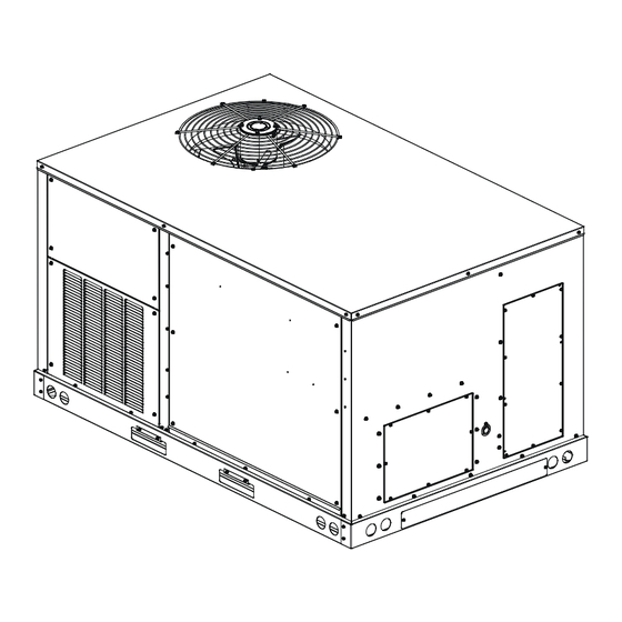
Packaged Air Conditioner And Heat Pump Unit 3-6 Ton
Direct Drive High Efficiency Light Commercial DHC/DHH
Models
Installation Instructions
NOTE: This equipment is only approved for use with
R-32 refrigerant.
Our continuing commitment to quality products may mean a change in specifications without notice.
IOD-1074
08/ 2024
©2024
19001 Kermier Rd., Waller, TX 77484
www.daikincomfort.com
INSTALLATION INSTRUCTIONS
ONLY PERSONNEL THAT HAVE BEEN TRAINED TO INSTALL,
ADJUST, SERVICE, MAINTENANCE OR REPAIR
(HEREINAFTER, "SERVICE") THE EQUIPMENT SPECIFIED IN
THIS MANUAL SHOULD SERVICE THE EQUIPMENT.
THIS EQUIPMENT IS NOT INTENDED FOR USE BY
PERSONS (INCLUDING CHILDREN) WITH REDUCED
PHYSICAL, SENSORY OR MENTAL CAPABILITIES, OR
LACK OF EXPERIENCE AND KNOWLEDGE, UNLESS THEY
HAVE BEEN GIVEN SUPERVISION OR INSTRUCTION
CONCERNING USE OF THE APPLIANCE BY A PERSON
RESPONSIBLE FOR THEIR SAFETY.
CHILDREN SHOULD BE SUPERVISED TO ENSURE THAT
THEY DO NOT PLAY WITH THE EQUIPMENT.
THE MANUFACTURER WILL NOT BE RESPONSIBLE FOR
ANY INJURY OR PROPERTY DAMAGE ARISING FROM
IMPROPER SUPERVISION, SERVICE OR SERVICE
PROCEDURES. IF YOU SERVICE THIS UNIT, YOU ASSUME
RESPONSIBILITY FOR ANY INJURY OR PROPERTY
DAMAGE WHICH MAY RESULT. IN ADDITION, IN
JURISDICTIONS THAT REQUIRE ONE OR MORE LICENSES
TO SERVICE THE EQUIPMENT SPECIFIED IN THIS
MANUAL, ONLY LICENSED PERSONNEL SHOULD
SERVICE THE EQUIPMENT. IMPROPER SUPERVISION,
INSTALLATION, ADJUSTMENT, SERVICING, MAINTENANCE
OR REPAIR OF THE EQUIPMENT SPECIFIED IN THIS
MANUAL, OR ATTEMPTING TO INSTALL, ADJUST, SERVICE
OR REPAIR THE EQUIPMENT SPECIFIED IN THIS MANUAL
WITHOUT PROPER SUPERVISION OR TRAINING MAY
RESULT IN PRODUCT DAMAGE, PROPERTY DAMAGE,
PERSONAL INJURY OR DEATH.
Do not bypass safety devices.
WARNING
WARNING
Advertisement
Table of Contents


Need help?
Do you have a question about the DHC Series and is the answer not in the manual?
Questions and answers