Table of Contents
Advertisement
Quick Links
Advertisement
Table of Contents

Related Manuals for ITW GSE 1400


Summary of Contents for ITW GSE 1400
- Page 1 28 VDC Ground Power Unit Serial no. Type www.itwgse.com 3GVF-200/260-N AXA Power, Hobart, Houchin, Military and J&B have become ITW GSE. As simply ITW GSE, we still offer the same premium products and service. SAME PEOPLE - SAME PRODUCTS - SAME COMPANY...
-
Page 2: Important Note
IMPORTANT NOTE We recommend that the battery that safeguards GPU settings etc. is changed after 5 years of use in order not to lose data. Refer to section 8.2 for further information Diagrams and drawings are subject to change without prior notice. Latest diagram versions can be found at www.itwgse.com Printed: March 2018 Document no. - Page 3 Abbreviations: Advanced Cable Retriever Active Rectifier Unit American Wire Gauge Building Management System Controller Area Network Dual In-Line Package Digital Signal Processor Earth Leakage Supervision Electromagnetic Compatibility Electromagnetic Interference Emergency Power Off Electro Static Discharge Ground Power Unit Ground Support Equipment IGBT Insulated Gate Bipolar Transistor Input/Output...
- Page 4 Types / Rating overview Part Type Rating Mounting Schematic Input voltage number 3GWF-28/400-N 400 A Fixed 543.302 443.400 3 x 400 +15% / -10% 3GWT-28/400-L 400 A Mobile 543.303 443.400 3 x 400 +15% / -10% 3GWT-28/600-S 600 A Skid 543.314 443.400 3 x 400 +15% / -10%...
-
Page 5: Table Of Contents
Operation Manual – ITW GSE 1400 28 VDC, 400A & 600A Index INDEX Declaration of Conformity ............... 7 Safety Instructions .................. 8 General Description................. 9 Built in features / protections ................13 Transport and Installation ..............14 Storage Before Installation ................14 Operational and Environmental Conditions after Commissioning .... - Page 6 Operation Manual – ITW GSE 1400 28 VDC, 400A & 600A Index Output Voltage Compensation (Feedback): ............. 45 Output Mode: ....................45 Interlock Bypass ....................45 EF Interlock Delay ................... 46 Aircraft Connector Insertion ................46 7.10 Cable Temperature ..................46 7.11...
-
Page 7: Declaration Of Conformity
Operation Manual – ITW GSE 1400 28 VDC, 400A & 600A Declaration of Conformity 1.0 Declaration of Conformity Document no. 543.300BB Page 7 of 61... -
Page 8: Safety Instructions
Operation Manual – ITW GSE 1400 28 VDC, 400A & 600A Safety Instructions IMPORTANT SAFEGUARDS DANGER – TO REDUCE THE RISK OF FIRE OR ELECTRIC SHOCK, CAREFULLY FOLLOW THESE INSTRUCTIONS Safety Instructions This unit is only intended to be installed, operated and maintained by competent persons having the necessary knowledge regarding delivery of external power to an aircraft. -
Page 9: General Description
General Description 3.0 General Description The figure below shows the basic principle of the ITW GSE 1400 Ground Power unit. The 50/60 Hz mains/utility voltage is rectified and via PWM sent to a galvanic isolated transformer. From the secondary of the transformer it’s rectified into a 28 VDC. A functional description of each part is given in the following sections. - Page 10 Operation Manual – ITW GSE 1400 28 VDC, 400A & 600A General Description 28 V GPU Board / Inverter Module (A2): Fig. 3.0.2 - 28 V GPU Board / Inverter Module The purpose of this board is to interface between the Control Board and the rest of the ground power unit.
- Page 11 Operation Manual – ITW GSE 1400 28 VDC, 400A & 600A General Description Output Transformer (T1): The output transformer ensures galvanic separation between input and output. It also transforms the voltages from the Inverter Module into the required level for the output rectifier.
- Page 12 Operation Manual – ITW GSE 1400 28 VDC, 400A & 600A General Description Display Board & Keyboard (A3 / A4): The display module serves as the interface for daily operation. The display communicates with the Control Board via a CAN bus and can be placed up to 100 m away from the unit, when using the Remote Control Box.
-
Page 13: Built In Features / Protections
Operation Manual – ITW GSE 1400 28 VDC, 400A & 600A General Description Built in features / protections Over/under voltage at input: The input voltage supervision is based on the rectified DC. The supervision ensures that the unit does not trip even in case of an abnormal low input voltage level. This of course presupposes that the 28 VDC output level and quality, required by the aircraft, can still be maintained. -
Page 14: Transport And Installation
Operation Manual – ITW GSE 1400 28 VDC, 400A & 600A Transport and Installation 4.0 Transport and Installation Storage Before Installation To secure optimal storage conditions prior to installation, we recommend that the converter is stored inside. This protects the unit from rain and excessive humidity while it is left without power. - Page 15 Operation Manual – ITW GSE 1400 28 VDC, 400A & 600A Transport and Installation Adequate lifting gear is not part of the delivery. Fig. 4.3.2 - Lifting with crane (Place M10 lifting rings at the 4 corners) Document no. 543.300BB...
-
Page 16: Installation And Fastening Instructions
Operation Manual – ITW GSE 1400 28 VDC, 400A & 600A Transport and Installation Installation and fastening instructions Fig. 4.4.1 - Footprint & spacing, fixed unit Fig. 4.4.2 - Mounting holes, fixed unit Document no. 543.300BB Page 16 of 61... - Page 17 Operation Manual – ITW GSE 1400 28 VDC, 400A & 600A Transport and Installation Fig. 4.4.3 - Cable entry point in base module Fig. 4.4.4 - Center of gravity Document no. 543.300BB Page 17 of 61...
-
Page 18: Connection Of Cables
Operation Manual – ITW GSE 1400 28 VDC, 400A & 600A Transport and Installation Connection of Cables X1/ X3 is standard X2 is optional Standard Remote I/O terminals (refer to section 4.8 for connection of I/O terminals) Fig. 4.5.1 - Connection of cables 50/60 Hz Input terminals: 3 x 35mm²... -
Page 19: Mains/Utility Input
63 A 63 A Due to the RFI filter at the input, the leakage current for the ITW GSE 1400 is > 135 mA. Interlock To ensure personnel health and safety, the converter is equipped with an interlock system. The system ensures that the output only stays engaged as long as the plug is inserted into the aircraft receptacle. -
Page 20: Control Interface (Remote I/O Terminals)
90 % Switch in aircraft connector (Optional). The 90% switch (N.O. contact set) in the aircraft connector is supplied with +24 VDC from the ITW GSE 1400. The voltage is returned once the plug is inserted at least 90% of the way into the aircraft receptacle. -
Page 21: Tcp/Ip On-Board Interface
Operation Manual – ITW GSE 1400 28 VDC, 400A & 600A Transport and Installation TCP/IP On-board Interface The ITW GSE 1400 is equipped with a TCP/IP (RJ45) communication port for supervision and monitoring of the GPU e.g. by the means of a central computer. The port is located on the Control Board (A1). -
Page 22: Technical Specifications
Operation Manual – ITW GSE 1400 28 VDC, 400A & 600A Technical Specifications Technical Specifications Standards: ISO 6858 Aircraft ground support electrical supplies - general requirements BS 2G 219 General requirements for ground support electrical supplies for aircraft MIL-704F Aircraft electric power characteristics (Machinery –... - Page 23 Operation Manual – ITW GSE 1400 28 VDC, 400A & 600A Technical Specifications Efficiency: Overall efficiency 0.87 Stand-by losses 130 W No-load losses 330W Protections: Input over-and under voltage Control voltage error Internal high temperature Output over-and under voltage Overload at output...
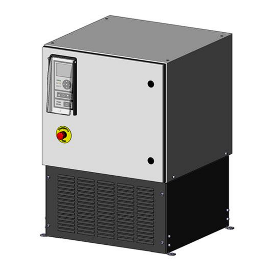
- Page 24 Operation Manual – ITW GSE 1400 28 VDC, 400A & 600A Technical Specifications Fixed Fig. 5.0.1 - Fixed unit Document no. 543.300BB Page 24 of 61...
- Page 25 Operation Manual – ITW GSE 1400 28 VDC, 400A & 600A Technical Specifications Mobile Fig. 5.0.2 - Mobile unit Document no. 543.300BB Page 25 of 61...
-
Page 26: Operator's Instructions (Display/Led/Keypad Layout)
Operation Manual – ITW GSE 1400 28 VDC, 400A & 600A Operator’s Instructions Operator’s Instructions (Display/LED/Keypad layout) Display Mains/utility On ”Blue” Navigation Warning keypad ”Yellow” LED Alarm/Failure ”Red” LED Current Limit Current Limit Decrease Increase Output 1 On Output ”Green” LED... -
Page 27: Using The Display/Keypad
Operation Manual – ITW GSE 1400 28 VDC, 400A & 600A Operator’s Instructions Using the Display/Keypad: To enable a smooth and easy operation, the operator control panel has a simple layout. The LED display is located at the top. It is used to provide information during operation / service / maintenance. It either... -
Page 28: Operating The Unit
Operation Manual – ITW GSE 1400 28 VDC, 400A & 600A Operator’s Instructions Operating the unit: To adapt the 28 VDC output power to different types of aircraft, it is possible to set a maximum DC current level in steps of 200 Amp (400 A Version) / 300 Amp (600 A version) using the... - Page 29 Operation Manual – ITW GSE 1400 28 VDC, 400A & 600A Operator’s Instructions Default Display Screen Standby 12:55.21 03-03-2017 28 V EF Bypassed Voltage: 0.0 V 28 V DC Ready For Use Current: Power: 0.0 kW 1500 A Back Use the to browse through the various screens.
- Page 30 Operation Manual – ITW GSE 1400 28 VDC, 400A & 600A Operator’s Instructions After operation, the unit has to be turned off before removing the aircraft plug. Press the Start/stop button The aircraft cable can now be removed from the aircraft and placed at the cable rest position.
-
Page 31: Basic Menu
Operation Manual – ITW GSE 1400 28 VDC, 400A & 600A Operator’s Instructions Basic Menu: Home Set-Up Black Box Save / Upload Power Log View Parameters The basic Icon Menu is shown above with the available sub-menus. ● from the default menu and hold it down for To enter the Icon Menu, press the approximately 10 seconds. -
Page 32: Parameters - Menu Structure
Operation Manual – ITW GSE 1400 28 VDC, 400A & 600A Operator’s Instructions 6.3.1 Parameters – Menu structure OUTPUT Voltage: 28.0 V Current: < 30 A Power: < 1 kW Interlock: 28.0 V Back Next/Prev INVERTER Phase A: < 20 A Phase B: <... -
Page 33: Setup - Menu Structure
Operation Manual – ITW GSE 1400 28 VDC, 400A & 600A Operator’s Instructions 6.3.2 Setup – Menu structure 11:27:47 Setup Menu 03-03-2017 Output Voltage Settings: 28.0 V 19.0 – 33.0 V Back Modify 11:27:47 Setup Menu 03-03-2017 11:27:47 Setup Menu... - Page 34 Operation Manual – ITW GSE 1400 28 VDC, 400A & 600A Operator’s Instructions Setup – Menu structure (continued) 11:27:47 Setup Menu 03-03-2017 EF Interlock Delay Settings: 3.5 s 1.0 – 120.0 sec. Back Modify 11:27:47 Setup Menu 03-03-2017 11:27:47 Setup Menu...
- Page 35 Operation Manual – ITW GSE 1400 28 VDC, 400A & 600A Operator’s Instructions Setup – Menu structure (continued) 11:27:47 Setup Menu 03-03-2017 Modbus Slave Address Settings: 1 - 247 Back Modify 11:27:47 Setup Menu 03-03-2017 11:27:47 Setup Menu 03-03-2017 Settings:...
-
Page 36: Black Box - Menu Structure
Operation Manual – ITW GSE 1400 28 VDC, 400A & 600A Operator’s Instructions 6.3.3 Black Box – Menu structure 14:54:33 03/03/2017 1000 SOFTSTART ERROR Alar m Data 001/100 28 V Voltage: 0.0 V Current: 14:54:33 Black Box 03/03/2017 Interlock: 0.0 V... -
Page 37: Power Log - Menu Structure
Operation Manual – ITW GSE 1400 28 VDC, 400A & 600A Operator’s Instructions 6.3.4 Power Log – Menu structure Power Log 001/100 Total Tim e: 22.0 Min. 0 – 5.7 kW Star t Date: 03/03/2017 5.7 – 11.4 kW Star t Time: 10:34 11.4 –... -
Page 38: Update Software / Save Logs / Load Config File
Operation Manual – ITW GSE 1400 28 VDC, 400A & 600A Operator’s Instructions 6.3.5 Update Software / Save Logs / Load Config File 10:30:00 USB MENU 03/03/2017 Update in Progress! Please Wait. Swapping Flash Blocks 10:30:00 USB MENU 03/03/2017 10:30:00... - Page 39 Operation Manual – ITW GSE 1400 28 VDC, 400A & 600A Operator’s Instructions Update Software / Save Logs / Load Config File (continued) 10:30:00 USB MENU 01/01/2017 Update in Progress! Do not turn off or reset during update! 10:30:00 USB MENU...
- Page 40 Operation Manual – ITW GSE 1400 28 VDC, 400A & 600A Operator’s Instructions Update software / Save Logs / Load Config File (continued) 10:30:00 USB MENU 03/03/2017 Saving log 10:30:00 USB MENU 03/03/2017 10:30:00 USB MENU 03/03/2017 Update Display Software...
- Page 41 Operation Manual – ITW GSE 1400 28 VDC, 400A & 600A Operator’s Instructions Update software / Save Logs / Load Config File (continued) 10:30:00 USB MENU 01/01/2017 Reading Flash Drive. Please Wait Press To Reset 10:30:00 USB MENU 01/01/2017 10:30:00...
-
Page 42: Incompatible Software Version
GSE representative ◄ Back ◄ Back ● Select Before changing software versions consult ITW GSE or if your intention really is to continue, as you already contacted / received the software files from ITW GSE, use below guidance to update software: 1. -
Page 43: Default Factory Settings
Operation Manual – ITW GSE 1400 28 VDC, 400A & 600A Operator’s Instructions Default Factory Settings: Output Voltage (V): 28.0 Current Limit (A): 1600 (400 A Version) / 2400 (600 A version) Compensation Type: Manual (Feedback if GPU supplied with cable) Output Compensation (V): 0.0 (Set if the GPU are supplied with cable) -
Page 44: Set-Up Lock / Output Mode / Compensation
Operation Manual – ITW GSE 1400 28 VDC, 400A & 600A Set-up Lock / Output Mode / Compensation Set-up Lock / Output Mode / Compensation Preventing changes of set-up parameters To avoid unintentional modification of the Set-up parameters, it is possible to block the access to the Set-up Mode, by means of a DIP switch situated at the Display Board A3. -
Page 45: Output Voltage Compensation (Feedback)
28VDC signal will not present, before provides 28 VDC power to the aircraft. The 28 VDC for aircraft connector is feed back to the Interlock input of the ITW GSE 1400. Go into the Setup Menu and then scroll up or down to the EF Interlock submenu. Press the center ●... -
Page 46: Ef Interlock Delay
Operation Manual – ITW GSE 1400 28 VDC, 400A & 600A Set-up Lock / Output Mode / Compensation Note! The value will be automatically reset to Active if the unit detects 28 volts on the "F" pin input of the I/O board. -
Page 47: Ethernet Configuration
Operation Manual – ITW GSE 1400 28 VDC, 400A & 600A Set-up Lock / Output Mode / Compensation Go into the Setup Menu and then scroll up or down to the Date/Time Format submenu. Press the center ● button to enter the submenu and then press the ● button again to allow the value to be changed. -
Page 48: Battery Replaced
Operation Manual – ITW GSE 1400 28 VDC, 400A & 600A Set-up Lock / Output Mode / Compensation character. Press the center ● button to record the new value. Press the LEFT arrow button to exit the submenu and return to the submenu list 7.18... -
Page 49: Service, Maintenance, Overhaul
Operation Manual – ITW GSE 1400 28 VDC, 400A & 600A Service, Maintenance, Overhaul Service, Maintenance, Overhaul To make certain that the unit always is ready for use it must be maintained on a regular basis. Only qualified personnel should remove covers for service, maintenance or overhaul... -
Page 50: Battery Back-Up & Replacement
Operation Manual – ITW GSE 1400 28 VDC, 400A & 600A Service, Maintenance, Overhaul Battery back-up & replacement Situated on the back of the control board, is a coin type lithium battery which ensures that Firmware / Set-up data etc. are not lost during mains/utility drop-outs. The expected life of the battery is approximately 7 years. -
Page 51: How To Change The Battery
Operation Manual – ITW GSE 1400 28 VDC, 400A & 600A Service, Maintenance, Overhaul To ensure high reliability of the back-up battery, the only type of battery that can be used on the Control Board is the Panasonic BR-2032 How to change the battery:... - Page 52 Operation Manual – ITW GSE 1400 28 VDC, 400A & 600A Service, Maintenance, Overhaul Battery holder and battery Fig. 8.2.4 - Control Board (rear view) Before you remove the battery from the holder, make sure that the replacement battery is within reach, as the Control Board must not be without battery power for more than 30 seconds.
-
Page 53: Trouble Shooting & Repair
Operation Manual – ITW GSE 1400 28 VDC, 400A & 600A Trouble Shooting & Repair Trouble Shooting & Repair Only have qualified personnel remove covers for trouble shooting and repair. Please be aware that the DC capacitors can remain charged to a dangerous voltage up to 5 minutes after the mains/utility input power has been disconnected. -
Page 54: Fault Guidance
Operation Manual – ITW GSE 1400 28 VDC, 400A & 600A Trouble Shooting & Repair Fault Guidance In case you need to contact us for further fault guidance, please do not forget to enter the serial number of the GPU (found at the rating plate) and the actual error code on the fault finding form that can be downloaded from www.itwgse.com. -
Page 55: Please Observe
Operation Manual – ITW GSE 1400 28 VDC, 400A & 600A Trouble Shooting & Repair Error code 2nd. Corrective action 3rd. Corrective action 4th. Corrective action Replace Control Board A1 Check input voltage Check Q1 & G1 Check input voltage Check Q1 &... -
Page 56: Illustrated Parts List
Operation Manual – ITW GSE 1400 28 VDC, 400A & 600A Illustrated Parts List 10.0 Illustrated Parts List Please refer to www.itwgse.com for recommended list of spare parts. It is also possible to find diagrams and drawings of the unit at this website A3/A4: Display &... - Page 57 Operation Manual – ITW GSE 1400 28 VDC, 400A & 600A Illustrated Parts List Exhaust filter grill R1: Resistor Output Rectifier T1: Output Transformer M1 – M2: Fans L1: Input Choke L2: Output Choke (located under heatsink) A2: 28 V GPU Board /...
-
Page 58: Options
Operation Manual – ITW GSE 1400 28 VDC, 400A & 600A Options 11.0 Options 543801 Additional Control Terminals (Diagram 443800) If additional control inputs / dry contacts are needed for additional control / indication to the PBB or to a... -
Page 59: 543802 Remote Control Box (Diagram 443400)
Operation Manual – ITW GSE 1400 28 VDC, 400A & 600A Options 543802 Remote Control Box (Diagram 443400) The control box is used for operation of the ground power unit, when the GPU is located away from the aircraft parking position. -
Page 60: 543805 Atr 1275 A Current Limit (Diagram 443800)
Operation Manual – ITW GSE 1400 28 VDC, 400A & 600A Options 543805 ATR 1275 A Current Limit (Diagram 443800) This option enables the user to set the current limit at 1275 A for the ATR aircraft, by switching the S20 switch to ATR selection. -
Page 61: 543807 Atr & 28 Vdc Voltage Adjust (Diagram 443800)
Operation Manual – ITW GSE 1400 28 VDC, 400A & 600A Options 543807 ATR & 28 VDC Voltage Adjust (Diagram 443800) This option combines the two options, ATR 1275 A current limit and the 28 VDC voltage adjust, as described at previous options. - Page 62 Title: Title: Title: Page: Page: Page: 1400 Series, 400 - 600 A 1400 Series, 400 - 600 A 1400 Series, 400 - 600 A Main Circuit and Instrumentation Main Circuit and Instrumentation Main Circuit and Instrumentation 1 ( 1 )
- Page 63 28 VDC Ground Power Unit Type: Type: Type: Title: Title: Title: Page: Page: Page: 1400-Series, Options 1400-Series, Options 1400-Series, Options Option Diagram Option Diagram Option Diagram 1 ( 1 ) 1 ( 1 ) 1 ( 1 ) Drawn: Drawn:...
- Page 64 This formula can be downloaded from www.itwgse.com Forward to Sender ITW GSE 1400 GPU information Americas: ITW GSE Americas Company : Type: + 1 941 721 1092 Fax: Serial No.: support@itwgse.us Phone: Error Code: International: ITW GSE ApS...
- Page 65 Title: Title: Title: Page: Page: Page: 1400 Series, 400 - 600 A 1400 Series, 400 - 600 A 1400 Series, 400 - 600 A Main Circuit and Instrumentation Main Circuit and Instrumentation Main Circuit and Instrumentation 1 ( 1 )
Need help?
Do you have a question about the 1400 and is the answer not in the manual?
Questions and answers
I would like to know, what is C2/C3/C4 ?
How much current does this require @ 208 V, 3- phse