TRENDnet TV-IP300 User Manual
Advanced wired/wireless day/night internet camera server
Hide thumbs
Also See for TV-IP300:
- Specifications (3 pages) ,
- Frequently asked questions manual (13 pages) ,
- Quick installation manual (11 pages)
Table of Contents
Advertisement
Quick Links
Advertisement
Table of Contents

Related Manuals for TRENDnet TV-IP300


Summary of Contents for TRENDnet TV-IP300
-
Page 2: Table Of Contents
..........51 NSTALLATION ABLE OF ONTENTS SP M .......53 NSTALLING ANUALLY SP ..........58 NINSTALLING SP – G ........61 ETTING TARTED SP............65 SING ABOUT THIS GUIDE ...........4 APPENDIX ..............72 INTRODUCTION ............5 IP U ...............72 TILITY ......74 REQUENTLY SKED UESTIONS ..........6 EATURES AND ENEFITS PING Y IP A... -
Page 3: About This Guide
BOUT UIDE NTRODUCTION This manual provides instructions and illustrations on how to use your Advanced Day/Night Internet Camera Server, includes: Chapter 1, Introduction, provides the general information on the camera. Thank you for purchasing the Advanced Day/Night Internet Camera Server, a standalone system that can be connected Chapter 2, Hardware Installation, describes the hardware directly to an Ethernet or Fast Ethernet. -
Page 4: Features And Benefits
Remote Utility Features and Benefits The powerful IPView SP application assigns the administrator with a pre-defined user ID and password, allowing the Simple To Use administrator to modify the camera’s settings from the remote site via Intranet or Internet. When new firmware is available, you can Advanced Day/Night Internet Camera Server is a also upgrade remotely over the network for added convenience. -
Page 5: Unpacking The Package
RS-485 Support Unpacking the Package The pin 5 & 6 of the I/O connectors are used for RS-485 data transmission. You can connect a special featured device (such as Unpack the package and check all the items carefully. In addition an external camera stand with rotation function) to meet you to this User’s Guide, be certain that you have: needs. -
Page 6: System Requirement
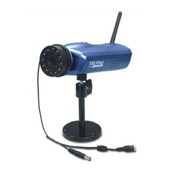
System Requirement Physical Description This section describes the externally visible features of the Networking camera. Local Area Network: 10Base-T Ethernet or 100Base-TX Fast Ethernet. Front Panel ① Link LED ④ Accessing the Camera Lens Assembly ② Power LED For Web Browser Users Operating System: Microsoft®... -
Page 7: Rear Panel
2. Power LED Rear Panel The Power LED is positioned on the far right side of the camera’s ① External Antenna lens while facing the camera. It is located on the right of the Link (for wireless model) LED. A steady Blue light confirms that the camera is powered on. - Page 8 3. Network Cable Connector Top/Bottom Panel The camera’s rear panel features an RJ-45 connector for Top Panel connections to 10Base-T Ethernet cabling or 100Base-TX Fast Screw Hole Ethernet cabling (which should be Category 5 twisted-pair cable). 4. I/O Connector The camera provides the I/O connectors on the rear panel (pin 1/2 are for input, pin 3/4 are for output, pin 5/6 are for RS-485), which provide the physical interface to send and receive digital signals to a variety of external alarm devices.
-
Page 9: Hardware Installation
Side Panel ARDWARE DC-Iris Connector NSTALLATION Attaching the Camera to the Stand DC-Iris Connector The camera comes with a The camera supports additional DC-Iris lens, and provides the camera stand (optional), which power and control signal required for adjusting the lens through has a swivel ball screw head that this DC-Iris connector (4-pin). -
Page 10: Connecting The Ethernet Cable
Connecting the Ethernet cable Replace the Lens Assembly Connect an Ethernet cable to the If required, you can replace the lens assembly with DC-Iris lens. network cable connector located First, remove the original lens by turning it in an anti-clockwise on the camera’s rear panel, and direction. -
Page 11: Security
ECURITY PPLICATION AMERA To ensure the highest security and prevent unauthorized usage of the camera, the administrator has the exclusive privilege to access the System Administration for settings and control requirements The camera can be applied in wide variety of applications. It is to allow users the level of entry and authorize the privileges for an all-in-one device that can be attached directly to an Ethernet or all users. -
Page 12: Applications
Application Diagrams of the Camera Applications 1. Home/Small Business Applications Monitor local and remote places and objects through a web browser, such as construction sites, hospitals, parks, schools and day-care centers. Capture single frame images or video images from the IPView SP application. -
Page 13: Using The Camera
2. I/O Connector Application SING THE AMERA You can access and manage the Advanced Day/Night Internet Camera Server through: 1) a web browser, and 2) the enclosed software IPView SP. This chapter describes the Web Configuration Utility, and provides the instructions on using the camera with a web browser. -
Page 14: Client Settings
Client Settings Default IP address Default IP Address Preview Area Pre-view area Welcome Screen of the Configuration Utility Under the Client Settings screen, the user can customize the configuration of the connected camera on individual platform, The Welcome screen will appear to provide the following two including the Media option and Protocol option. -
Page 15: System Administration
System System Administration The System window contains commands for settings that are required for inputting key details to set up the camera for Under the Welcome screen of the Configuration Utility, click operation. System Administration to enter the administration window that contains the settings required for the camera in the top menu bar, including System, Video, Users, DateTime, Motion detection, TIP:... - Page 16 Dynamic DNS The default setting for Admin is blank space (Null String). For security purpose, you are strongly recommended to set the Admin Check the Enable option to enable the Dynamic DNS function, Password (a maximum of 8 characters) as soon as possible to which allows you to run your domain over a changing IP address.
- Page 17 respectively; the camera will automatically pad your input to settings are Infrastructure mode and Ad-Hoc mode. a bit count of 64 or 128. default setting is Infrastructure. HEX input format: Channel: The pull-down menu provides the wireless channel Hex format causes each pair of characters you type to be for communication.
- Page 18 Video • Local FTP server port - The standard port number for the FTP server is Port 21, and it’s also the default setting. The Video window contains commands to provide the settings for If the FTP server uses a specific port, please confirm the the images captured by the camera.
- Page 19 Frame Rate Users Select the optimal setting depending on your network status. The User window contains commands that allow the system Please note that the higher setting can obtain better quality; administrator to assign legal users who are permitted to monitor however, it will use more resource within your network.
- Page 20 User Password: Enter the user’s password assigned by the DateTime administrator (a maximum of 8 characters, printable ASCII code). The DateTime window contains commands to set up the camera's time and date, providing correct information to the remote users I/O Output Control: The administrator has the authority to who might be thousands of miles away from the camera’s give permission for the privilege to control the I/O Output location.
-
Page 21: Motion Detection
• TimeZone – Select the time zone for the region from the Motion Detection pull-down menu. (Please refer to the Appendix for the time zone selection table.) The Motion Detection window contains Set Manually: Select this option to set the time manually. Click Motion Detection in the top menu bar and the Motion The system administrator must enter the Date and Time in the Detection window will appear as below:... - Page 22 I/O Input Trigger Application This item is used to set up the following related action(s) when The Application window contains commands for the I/O Trigger the camera receives the signal from the I/O Input Trigger, connectors, providing the physical interface for two digital including Trigger I/O output, Send snapshot image by email and output/input to connect a diversity of external alarm devices, such Upload snapshot image to FTP server.
-
Page 23: Rs485 Port
RS485 Port The RS485 Port window contains the control settings for external device through the I/O port. You have to configure the respective settings in this window. Click RS485 Port in the top menu bar and the RS485 Port window will appear as below: Control buttons Port Setting Select the proper values from the pull-down menus in this... - Page 24 Firmware Version Information The field displays the firmware version of the camera. The Information window provides detailed information of the camera, including the Model Name, Firmware Version, Mac MAC Address Address, IP Address and System Log. This field displays the MAC Address of the camera. Click Information in the top menu bar and the Information window will appear as below: IP Address...
- Page 25 Factory Reset: Tools Do you really want to factory reset this device? Click YES from The Tools window contains commands for restarting the camera. this option, and you can resume all factory default settings for the camera. If you do not want to restore the factory settings, exit Click Tools in the top menu bar and the Tools window will this window without clicking YES.
-
Page 26: Controlling I/O Output Trigger
Controlling I/O Output Trigger On the Home screen of Configuration Utility, you can turn on/off the output device manually by clicking the ON/OFF button. This chapter describes the IPView SP, which is a powerful software application designed with a user-friendly interface for ease of control and navigation requirements. -
Page 27: Installing Ipview Sp Manually
Then, select the desired options from the menu buttons, including Installing IPView SP Manually the following options: • Users Guide If the Auto-Run program doesn’t launch automatically, you can • IPView SP install IPView SP manually. • IP Utility 1. On the Windows desktop, click Start at the taskbar and •... - Page 28 4. Choose the destination location. If no specific requirement, leave the default setting and click Next. Click Click 3. Read and accept the software’s License Agreement; then, 5. Select the program folder. If no specific requirement, leave click Yes. the default setting and click Next. Click Click...
- Page 29 8. Click Finish to complete the installation. The InstallShield Wizard starts to install the software. The Progress bar indicates the installation is proceeding. Click 7. If you use Windows® 2000/XP, it will appear a Digital Signature warning screen. Click Yes (Windows® 2000) or TIP: If you use Windows 98SE/ME, the system will ask you to Continue Anyway (Windows®...
-
Page 30: Uninstalling Ipview Sp
Uninstalling IPView SP Double-click To uninstall IPView SP: 1. Click Start and select Programs > IPViewSP, and then click Uninstall IPViewSP. Select Click Click Click 2. Select Uninstall and click Next when the InstallShield Wizard asks you to select the Setup type. Alternately, you can click Start and select Settings, and then select Control Panel to open the Control Panel window. -
Page 31: Ipview Sp - Getting Started
3. Click OK when prompted to confirm uninstall. IPView SP – Getting Started This section describes the operation of the IPView SP application User Interface with detailed procedures for using the application. Click Launching IPView SP 4. The InstallShield Wizard starts to uninstall the software. To start running IPView SP, click Start and select Programs >... - Page 32 Connecting This area provides four buttons to control the connect Control Area status of camera. The four buttons include: Assign, Connect/Disconnect, Erase, and Camera Setting. - Assign: Click to enter the IP Address (default setting: 192.168.0.30) of the camera in the pop-up dialog box.
-
Page 33: Using Ipview Sp
System This button is used to configure the system settings. Using IPView SP Configuration Play Click to bring up IPView SP Player to play the Adding a Camera recorded video clip. Help Click to bring up the help window. To add a new camera: 1. -
Page 34: Removing A Camera
Viewing the Camera Select From the Display screen, you can choose One Camera Mode or Four Camera Mode to display your video. A maximum of 4 cameras are available for viewing with the IPView SP. example, if you use only one camera, click One Camera Mode button to display the video as figure 1. -
Page 35: Recording Video
When multiple cameras connected, you can choose Scan Mode button to display these videos as the main view in circles. Capturing Image IPView SP allows you to capture a still image and save it to your hard disk drive. To capture the image, simply click Snapshot button and select the folder you want to save the image. -
Page 36: Configuring The System
change the current path setting; click Add to add a new Configuring the System destination folder; click Delete to remove a selected path Click the System Configuration button on IPView SP screen, and setting. Please note that you are not allowed to delete a you can configure the settings of you camera. -
Page 37: Appendix
The connected camera(s) list. PPENDIX Information of A IP Utility selected camera. The Advanced Day/Night Internet Camera Server provides you with a convenient tool - IP Utility, which will help you search the connected Internet Camera(s) within your network easily and quickly. -
Page 38: B Frequently Asked Questions
About Internet Camera Installation B Frequently Asked Questions Q: Can the Advanced Day/Night Internet Camera Server be About Advanced Day/Night Internet Camera used out-doors? Server Features A: The camera is not weatherproof. It needs to be equipped with a weatherproof case to be used outdoors and it is not recommended. -
Page 39: Cping Your Ip Address
C PING Your IP Address D Troubleshooting The PING (Packet Internet Groper) command can determine Q: I cannot access the Advanced Day/Night Internet Camera whether a specific IP address is accessible by sending a packet to Server from a web browser. the specific address and waiting for a reply. - Page 40 The other possible problems might be due to the network cable. Q: Why does a series of broad vertical white line appear Try replacing your network cable. Test the network interface of through out the image? the product by connecting a local computer to the unit, utilizing a A: A likely issue is that the CMOS sensor becomes overloaded standard Crossover (hub to hub) Cable.
-
Page 41: E Time Zone Table
Otherwise, the configuration of the camera’s image display is Time Zone Table incorrect. You need to adjust the related parameter for improving images through the Preview window under Web Configuration Utility, such as brightness, contrast, hue and light frequency. Please refer to the Web Configuration section for details. Q: There are no images available through the web browser? A: The ActiveX might be disabled. -
Page 42: F Adjusting Camera Focus
Adjusting Camera Focus The Advanced Day/Night Internet Camera Server features an exchangeable CS-type lens that can be used for different applications as necessary. It supports rotational focus control, so that the lens can be adjusted to focus under normal and stable conditions to maximize the image quality of the camera. -
Page 43: G Specification
NOTE: You can further adjust the camera's image quality G Specification through the Preview window under Web Configuration Utility. Please refer to Web Configuration section for further details. Image Sensor Resolution: 512x480 (NTSC), 512x576 (PAL) Sensor: Sharp 1/4” type CCD WARNING: Direct exposure to sunlight may cause permanent Lens assembly: damage to the CMOS sensor. - Page 44 System Hardware Operating Environment CPU: Philips Trimedia PNX1300 VLIW DSP Operating temperature: 5°C ~ 40°C RAM: 16MB Storage temperature: -25°C ~ 60°C Flash ROM: Humidity: 5% ~ 95% non-condensing Embedded Linux LAN Connector: One RJ-45 port to connect to 10/100Mbps Ethernet, auto-sensed FCC, CE, VCCI Class B Wireless LAN: IEEE 802.11g wireless LAN...
-
Page 45: H Glossary Of Terms
H Glossary of Terms BOOTP Bootstrap Protocol is an Internet protocol that can automatically configure a network device in a diskless NUMBERS workstation to give its own IP address. 10BASE-T 10BASE-T is Ethernet over UTP Category III, IV, or V unshielded twisted-pair media. 100BASE-TX two-pair twisted-media... - Page 46 allows the specification for the service provided by a or 100Mbps per second over UTP, STP, or fiber-optic router, gateway, or other network device that media. automatically assigns an IP address to any device that requests one Firewall Firewall is considered the first line of defense in Domain Name System is an Internet service that protecting private information.
- Page 47 ISP (Internet Service Provider) is a company that maintains a network that is linked to the Internet by Intranet This is a private network, inside an organization or way of a dedicated communication line. An ISP offers company that uses the same software you will find on the use of its dedicated communication lines to the public Internet.
- Page 48 network request information from the Internet, the Protocol Communication on the network is governed by sets of requests are forwarded to the Internet under the rules called protocols. Protocols provide the guidelines router's IP address. NAT distributes the responses to devices use to communicate with each other, and thus the proper IP addresses within your network.
- Page 49 Router A router is the network software or hardware entity Transceiver A transceiver joins two network segments together. charged with routing packets between networks. Transceivers can also be used to join a segment that uses one medium to a segment that uses a different medium.
-
Page 50: Limited Warranty
Windows Windows is a graphical user interface for workstations Limited Warranty that use DOS. Workgroup A workgroup is a group of users who are physically TRENDware warrants its products against defects in material and workmanship, located together and connected to the same LAN, or a under normal use and service, for the following lengths of time from the date of purchase. -
Page 51: Technical Support
FOR DAMAGES WILL NOT BE AFFECTED IF ANY REMEDY PROVIDED HEREIN SHALL FAIL OF ITS ESSENTIAL PURPOSE. Governing Law: This Limited Warranty shall be governed by the laws of the state E-mail: support@trendware.com of California. www.TRENDnet.com Monday ~ Friday, 7:30AM ~ 6:00PM Pacific Standard Time (Except holidays)
Need help?
Do you have a question about the TV-IP300 and is the answer not in the manual?
Questions and answers