
Related Manuals for schmersal AZM300Z-I2-ST-1P2P-A-DU


Summary of Contents for schmersal AZM300Z-I2-ST-1P2P-A-DU
-
Page 1: Table Of Contents
INSTRUÇÕES DE OPERAÇÃO E MONTAGEM Encravamento de segurança AZM300Z-I2-ST-1P2P-A-DU Table of Contents 1 About this document 1.1 Function 1.2 Target group of the operating instructions: authorised qualified personnel 1.3 Explanation of the symbols used 1.4 Appropriate use 1.5 General safety instructions 2 Product description 2.1 Ordering code... -
Page 2: Function
Warning: Failure to comply with this warning notice could lead to physical injury and/or damage to the machine. 1.4 Appropriate use The Schmersal range of products is not intended for private consumers. The products described in these operating instructions are developed to execute safety-related functions as part of an entire plant or machine. -
Page 3: Product Description
Further technical information can be found in the Schmersal catalogues or in the online catalogue on the Internet: products.schmersal.com. 2 Product description 2.1 Ordering code Product type description: AZM300(1)-(2)-ST-(3)-(4)-(5) > Guard locking monitored Actuator monitored without Standard coding Individual coding... -
Page 4: Purpose
2.3 Purpose The non-contact, electronic safety switchgear is designed for application in safety circuits and is used for monitoring the position and locking of movable safety guards. The safety switchgears are classified according to EN ISO 14119 as type 4 interlocking devices. Designs with individual coding are classified as highly coded. -
Page 5: Technical Data
2.6 Technical Data Homologações - Instruções TÜV Certificados cULus ECOLAB UKCA ANATEL Propriedades globais Instruções EN ISO 13849-1 EN ISO 14119 EN IEC 60947-5-3 EN IEC 61508 informação gerais Codificação individual, aprendizagem múltipla Nível de codificação conforme EN ISO 14119 Alto Princípio ativo RFID... - Page 6 Indicação integrada, estado Número de direções de atuação Quantidade de saídas digitais seguras Classificação Certificados EN ISO 13849-1 EN IEC 61508 Classificação - função de solenóide adicional Performance Level, até Categoria de comando Valor PFH 5,20 x 10⁻¹⁰ /h Valor PFD 4,50 x 10⁻⁵...
- Page 7 Distância do interruptor, típico 2 mm Distância do interruptor garantida "ON" S 1 mm Distância do interruptor garantida "OFF" S 20 mm Dados mecânicos - Tecnologia conectiva Comprimento da corrente de sensores, máximo 200 m Nota (comprimento da cadeia de sensores) O comprimento e a secção do cabo alteram a queda de tensão em função da corrente de saída Nota (ligação em série)
- Page 8 Tensão de operação 24 VDC -15 % / +10 % Corrente de circuito aberto I , típico 100 mA Consumo de corrente com o íman ON, valor médio 200 mA Consumo de corrente com íman ON, valor de pico 350 mA / 200 ms Medição da tensão de operação 24 VDC Corrente operacional nominal...
- Page 9 Designação, saídas de segurança Y1 e Y2 Versão de elementos de comutação À prova de curto-circuito, tipo p Queda de tensão U , máximo Corrente residual I , máximo 0,5 mA Voltagem, categoria de aplicação DC-12 24 VDC Potência, categoria de aplicação DC-12 0,25 A Voltagem, categoria de aplicação DC-13 24 VDC...
- Page 10 This device complies with the nerve stimulation limits (ISED CNR-102) when operated at a minimum distance of 100 In the event of changes or modifications that have not been expressly approved by K.A. Schmersal GmbH & Co. KG, the user's authorisation to use the device may become ineffective.
-
Page 11: Mounting
3 Mounting 3.1 General mounting instructions Please observe the remarks of the standards EN ISO 12100, EN ISO 14119 and EN ISO 14120. For the correct fixing of the solenoid interlock and the actuator, two mounting holes for M6 screws are provided (tightening torque: 6 …... - Page 12 The diagrams show a closed guard system with a set latching force of 50 N (see also chapter "adjustment of latching force"). Provide for a sufficient insertion of the actuator into the rotary handle. Correct False To avoid any interference inherent to this kind of system and any reduction of the switching distances, please observe the following guidelines: The presence of metal chips in the vicinity of the solenoid interlock is liable to modify the switching distance Keep away from metal chips...
- Page 13 Minimum distance between two solenoid interlocks as well as other systems with same frequency (125 kHz) The minimum distance from metallic securing surfaces to the face side "A" and underside "B" of the device is 5 mm. 13-32...
-
Page 14: Manual Release
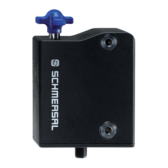
3.2 Manual release For the machine set-up, the solenoid interlock can be unlocked in a de-energised condition. The solenoid interlock is unlocked by turning the manual release in the position The normal locking function is only restored after the manual release has been returned to its original position Caution: do not turn beyond the end stop! A: connector plug M12, 8-pole B: LED display... -
Page 15: Mounting With Mounting Plate
Reset of the manual release by actuating the red emergency exit lever must be prevented by the user. Emergency exit (-T/-T8) fitting and actuation only from within the hazardous area To activate the emergency exit, turn the red lever in the direction of the arrow to the end stop. The safety outputs switch off and the guard system can be opened. -
Page 16: Dimensions
3.5 Dimensions All measurements in mm. AZM300...-T/-T8 and -N Device with emergency exit or emergency release Emergency exit -T / Emergency release -N 16-32... - Page 17 Emergency exit -T8 17-32...
-
Page 18: Actuator And Accessories
3.6 Actuator and accessories Actuator AZ/AZM300-B1 (not included in delivery) Mounting plate MP-AZ/AZM300-1 (available as accessory) 18-32... - Page 19 MS-AZ/AZM300-B1-1 (available as accessory) Aluminium protective plate as a cover for use on glass and plastic doors on machines with high design requirements Lockout tag SZ 200-1 (available as accessory) 19-32...
-
Page 20: Electrical Connection
Bowden cable release ACC-AZM300-BOW-.-.M-.M (available as accessory) Observe the additional notes in the operating instructions of the Bowden cable release. 4 Electrical connection 20-32... -
Page 21: General Information For Electrical Connection
The safety-monitoring module does not need to have a cross-wire short monitoring function, if necessary, the cross-wire short monitoring function must be disabled. Information for the selection of suitable safety-monitoring modules can be found in the Schmersal catalogues or in the online catalogue on the Internet: products.schmersal.com 4.2 Serial diagnostic -SD... - Page 22 Wiring example 1: Series-wiring of the AZM300 with conventional diagnostic output The voltage is supplied at both safety inputs of the terminal safety component of the chain (considered from the safety-monitoring module). The safety outputs of the first safety component are wired to the safety-monitoring module.
-
Page 23: Wiring Configuration And Connector Accessories
Y1 and Y2 = Safety outputs → Safety monitoring module SD-IN → Gateway → Field bus 4.4 Wiring configuration and connector accessories 23-32... -
Page 24: Actuator Coding And Latching Force Adjustment
Function safety switchgear Colour codes of the Schmersal Poss. colour configuration connectors code of other of the commercially connector available connectors according to EN 60947-5-2 With With serial IP67 / IP69 IP69 conventional diagnostic to DIN 47100 (PVC) -
Page 25: Latching Force Adjustment
Solenoid interlocks with standard coding are ready to use upon delivery. Individually coded solenoid interlocks and actuators will require the following "teach-in" procedure: 1. Switch the solenoid interlock's voltage supply off and back on. 2. Introduce the actuator in the detection range. The teach-in procedure is signalled at the solenoid interlock, green LED off, red LED on, yellow LED flashes (1 Hz). -
Page 26: Diagnostic-Leds
In the standard AZM300Z variant, the unlocking of the solenoid interlock causes the safety outputs to be disabled. The unlocked safety guard can be relocked as long as the actuator is inserted in the AZM300Z solenoid interlock; in that case, the safety outputs are re-enabled. It is not necessary to open the safety guard. - Page 27 Normal sequence, door was locked Door could not be locked or fault Legend Safety guard open Safety guard closed Locking time Safety guard not locked or fault Safety guard locked Lock Unlock ...
- Page 28 Safety guard can be locked Safety guard locked Power to lock: IN = 1 = Lock Safety guard can be locked Safety guard locked 28-32...
- Page 29 Table 1: Diagnostic information of the safety switchgear Diagnostic Magnet control IN Safety outputs Y1, Y2 output OUT System condition Power to Power to green yellow AZM300Z AZM300B unlock lock Safety guard 24 V (0 V) 0 V (24 V) open Safety guard 24 V...
-
Page 30: Solenoid Interlock With Serial Diagnostic Function Sd
In this way, the diagnostic signals can be evaluated by means of a PLC. The necessary software for the integration of the SD-Gateway is available for download at products.schmersal.com. The response data and the diagnostic data are automatically and permanently written in an input byte of the PLC for each solenoid interlock in the series-wired chain. -
Page 31: Set-Up And Maintenance
Diagnostic error (warning) If an error (warning) is signalled in the response byte, detailed fault information can be read out. Table 3: I/O data and diagnostic data (The described condition is reached, when Bit = 1) Diagnostic error Bit n° Call Byte Response-Byte Diagnostic error... -
Page 32: Disassembly And Disposal
32-32 ACE Schmersal Eletroeletrônica Ind. Ltda, Av. Brasil, nº 815, Jardim Esplanada – CEP 18557-646 Boituva/SP Os dados e informações fornecidas foram cuidadosamente verificados. No entanto as imagens podem divergir do original. Informações técnicas adicionais podem ser encontradas no manual. Alterações técnicas e erros são possíveis.
Need help?
Do you have a question about the AZM300Z-I2-ST-1P2P-A-DU and is the answer not in the manual?
Questions and answers